CYLINDER HEAD > REPLACEMENT

for Preparation Click here


1. REPLACE INTAKE VALVE GUIDE BUSH
  1. Heat the cylinder head to 80 to 100°C (176 to 212°F).

  1. Place the cylinder head on wooden blocks.


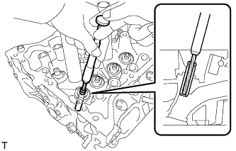
    A150967E01
  1. Using SST and a hammer, tap out the guide bush.
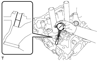
    SST
    09201-10000   (09201-01050)
    09950-70010   (09951-07100)


    A152649
  1. Using a caliper gauge, measure the bush bore diameter of the cylinder head.

    Standard cylinder bore diameter:
    10.285 to 10.306 mm (0.405 to 0.406 in.)

    Select New Guide Bush:
    Bush Size
    Bush Diameter
    STD
    10.333 to 10.344 mm (0.4068 to 0.4072 in.)
    O/S 0.05
    10.383 to 10.394 mm (0.4088 to 0.4092 in.)

    If the bush bore diameter of the cylinder head is more than 10.306 mm (0.406 in.), machine the bush bore to a diameter of 10.335 to 10.356 mm (0.407 to 0.408 in.) in order to install an O/S 0.05 valve guide bush. If the bush bore diameter of the cylinder head is more than 10.356 mm (0.408 in.), replace the cylinder head.

  1. Heat the cylinder head to 80 to 100°C (176 to 212°F).

  1. Place the cylinder head on wooden blocks.


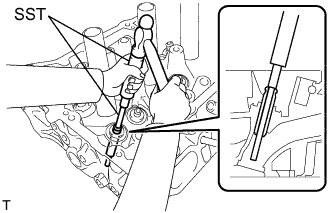
    A150969E02
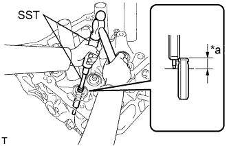
  1. Using SST and a hammer, tap in a new guide bush to the specified protrusion height.
    Text in Illustration 
    *a
    Height

    SST
    09201-10000   (09201-01050)
    09950-70010   (09951-07100)

    Standard protrusion height:
    9.9 to 10.3 mm (0.390 to 0.406 in.)


    A150971
  1. Using a sharp 5.5 mm reamer, ream the guide bush to obtain the standard clearance between the guide bush and valve stem.

    Standard oil clearance:
    0.025 to 0.060 mm (0.000984 to 0.00236 in.)


2. REPLACE EXHAUST VALVE GUIDE BUSH
  1. Heat the cylinder head to 80 to 100°C (176 to 212°F).

  1. Place the cylinder head on wooden blocks.


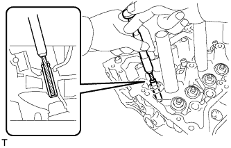
    A150968E01
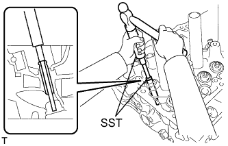
  1. Using SST and a hammer, tap out the guide bush.
    SST
    09201-10000   (09201-01050)
    09950-70010   (09951-07100)


    A152650
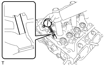
  1. Using a caliper gauge, measure the bush bore diameter of the cylinder head.

    Standard cylinder bore diameter:
    10.285 to 10.306 mm (0.405 to 0.406 in.)

    Select New Guide Bush:
    Bush Size
    Bush Diameter
    STD
    10.333 to 10.344 mm (0.4068 to 0.4072 in.)
    O/S 0.05
    10.383 to 10.394 mm (0.4088 to 0.4092 in.)

    If the bush bore diameter of the cylinder head is more than 10.306 mm (0.406 in.), machine the bush bore to a diameter of 10.335 to 10.356 mm (0.407 to 0.408 in.) in order to install an O/S 0.05 valve guide bush. If the bush bore diameter of the cylinder head is more than 10.356 mm (0.408 in.), replace the cylinder head.

  1. Heat the cylinder head to 80 to 100°C (176 to 212°F).

  1. Place the cylinder head on wooden blocks.
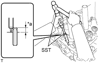


    A150970E02
  1. Using SST and a hammer, tap in a new guide bush to the specified protrusion height.
    Text in Illustration 
    *a
    Height

    SST
    09201-10000   (09201-01050)
    09950-70010   (09951-07100)

    Standard protrusion height:
    11.15 to 11.55 mm (0.439 to 0.455 in.)


    A150972
  1. Using a sharp 5.5 mm reamer, ream the guide bush to obtain the standard clearance between the guide bush and valve stem.

    Standard oil clearance:
    0.030 to 0.065 mm (0.00118 to 0.00256 in.)


3. REPLACE RING PIN

NOTICE:
It is not necessary to remove a ring pin unless it is being replaced.

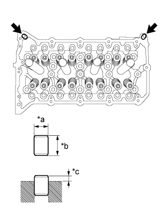
  1. Remove the ring pins.


    A150959E08
  1. Using a plastic-faced hammer, tap in a new ring pin to the specified protrusion height.
    Text in Illustration 
    *a
    Width
    *b
    Height
    *c
    Protrusion Height

    Standard Ring Pin:
    Item
    Height
    Width
    Protrusion
    Ring pin
    11.7 to 12.3 mm (0.461 to 0.484 in.)
    12.0 mm (0.472 in.)
    6.5 to 7.5 mm (0.256 to 0.295 in.)