LIN COMMUNICATION SYSTEM > TERMINALS OF ECU |
| CHECK MAIN BODY ECU (MULTIPLEX NETWORK BODY ECU) |
Disconnect the 2C and 2B instrument panel junction block assembly connectors.
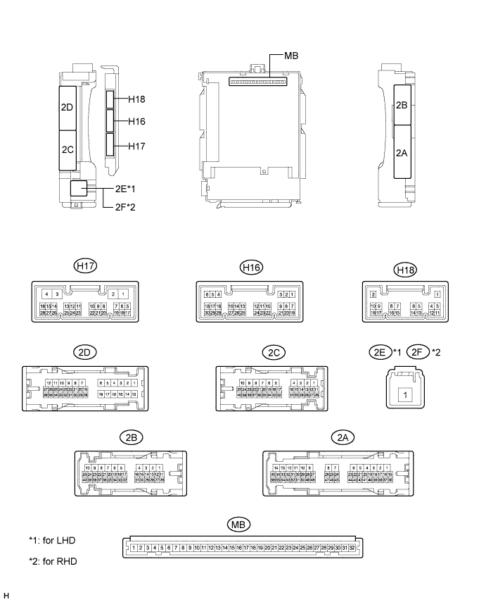
Measure the voltage and resistance according to the value(s) in the table below.
| Tester Connection | Wiring Color | Terminal Description | Condition | Specified Condition |
| 2C-18 (BECU) - Body ground | B - Body ground | Auxiliary battery power supply | Power switch off | 11 to 14 V |
| 2B-6 (GND1) - Body ground | W-B - Body ground | Ground | Always | Below 1 Ω |
Reconnect the 2C and 2B instrument panel junction block assembly connectors.
Check for pulses according to the value(s) in the table below.
| Tester Connection | Wiring Color | Terminal Description | Condition | Specified Condition |
| 2D-26 (LIN2) - 2B-6 (GND1) | P - W-B | LIN communication line | Power switch on (IG) | Pulse generation |
| 2A-27 (LIN2) - 2B-6 (GND1) | P - W-B | LIN communication line | Power switch on (IG) | Pulse generation |
| CHECK POWER WINDOW REGULATOR MOTOR ASSEMBLY (for Driver Side) |
Disconnect the K2*1 or J2*2 power window regulator motor assembly (for driver side) connector.

| *A | for LHD | *B | for RHD |
Measure the voltage and resistance according to the value(s) in the table below.
| Tester Connection | Wiring Color | Terminal Description | Condition | Specified Condition |
| K2-2 (B) - K2-1 (GND) | L - W-B | Auxiliary battery power supply | Power switch off | 11 to 14 V |
| K2-1 (GND) - Body ground | W-B - Body ground | Ground | Always | Below 1 Ω |
| Tester Connection | Wiring Color | Terminal Description | Condition | Specified Condition |
| J2-2 (B) - J2-1 (GND) | L - W-B | Auxiliary battery power supply | Power switch off | 11 to 14 V |
| J2-1 (GND) - Body ground | W-B - Body ground | Ground | Always | Below 1 Ω |
Reconnect the K2*1 or J2*2 power window regulator motor assembly (for driver side) connector.
Check for pulses according to the value(s) in the table below.
| Tester Connection | Wiring Color | Terminal Description | Condition | Specified Condition |
| K2-9 (LIN) - K2-1 (GND) | B - W-B | LIN communication line | Power switch on (IG) | Pulse generation |
| Tester Connection | Wiring Color | Terminal Description | Condition | Specified Condition |
| J2-9 (LIN) - J2-1 (GND) | L - W-B | LIN communication line | Power switch on (IG) | Pulse generation |
| CHECK POWER WINDOW REGULATOR MOTOR ASSEMBLY (for Front Passenger Side) |
Disconnect the J2*1 or K2*2 power window regulator motor assembly (for front passenger side) connector.

| *A | for LHD | *B | for RHD |
Measure the voltage and resistance according to the value(s) in the table below.
| Tester Connection | Wiring Color | Terminal Description | Condition | Specified Condition |
| J2-2 (B) - J2-1 (GND) | L - W-B | Auxiliary battery power supply | Power switch off | 11 to 14 V |
| J2-1 (GND) - Body ground | W-B - Body ground | Ground | Always | Below 1 Ω |
| Tester Connection | Wiring Color | Terminal Description | Condition | Specified Condition |
| K2-2 (B) - K2-1 (GND) | L - W-B | Auxiliary battery power supply | Power switch off | 11 to 14 V |
| K2-1 (GND) - Body ground | W-B - Body ground | Ground | Always | Below 1 Ω |
Reconnect the J2*1 or K2*2 power window regulator motor assembly (for front passenger side) connector.
Check for pulses according to the value(s) in the table below.
| Tester Connection | Wiring Color | Terminal Description | Condition | Specified Condition |
| J2-9 (LIN) - J2-1 (GND) | P - W-B | LIN communication line | Power switch on (IG) | Pulse generation |
| Tester Connection | Wiring Color | Terminal Description | Condition | Specified Condition |
| K2-9 (LIN) - K2-1 (GND) | P - W-B | LIN communication line | Power switch on (IG) | Pulse generation |
| CHECK POWER WINDOW REGULATOR MOTOR ASSEMBLY (for Rear RH Side) |
Disconnect the L2 power window regulator motor assembly (for rear RH side) connector.

Measure the voltage and resistance according to the value(s) in the table below.
| Tester Connection | Wiring Color | Terminal Description | Condition | Specified Condition |
| L2-2 (B) - L2-1 (GND) | R - W-B | Auxiliary battery power supply | Power switch off | 11 to 14 V |
| L2-1 (GND) - Body ground | W-B - Body ground | Ground | Always | Below 1 Ω |
Reconnect the L2 power window regulator motor assembly (for rear RH side) connector.
Check for pulses according to the value(s) in the table below.
| Tester Connection | Wiring Color | Terminal Description | Condition | Specified Condition |
| L2-9 (LIN) - L2-1 (GND) | P - W-B | LIN communication line | Power switch on (IG) | Pulse generation |
| CHECK POWER WINDOW REGULATOR MOTOR ASSEMBLY (for Rear LH Side) |
Disconnect the M2 power window regulator motor assembly (for rear LH side) connector.

Measure the voltage and resistance according to the value(s) in the table below.
| Tester Connection | Wiring Color | Terminal Description | Condition | Specified Condition |
| M2-2 (B) - M2-1 (GND) | R - W-B | Auxiliary battery power supply | Power switch off | 11 to 14 V |
| M2-1 (GND) - Body ground | W-B - Body ground | Ground | Always | Below 1 Ω |
Reconnect the M2 power window regulator motor assembly (for rear LH side) connector.
Check for pulses according to the value(s) in the table below.
| Tester Connection | Wiring Color | Terminal Description | Condition | Specified Condition |
| M2-9 (LIN) - M2-1 (GND) | P - W-B | LIN communication line | Power switch on (IG) | Pulse generation |
| CHECK MULTIPLEX NETWORK MASTER SWITCH ASSEMBLY |
Disconnect the K5*1 or J9*2 multiplex network master switch assembly connector.

| *A | for LHD | *B | for RHD |
Measure the voltage and resistance according to the value(s) in the table below.
| Tester Connection | Wiring Color | Terminal Description | Condition | Specified Condition |
| K5-11 (B) - K5-12 (GND) | L - W-B | Auxiliary battery power supply | Power switch off | 11 to 14 V |
| K5-12 (GND) - Body ground | W-B - Body ground | Ground | Always | Below 1 Ω |
| Tester Connection | Wiring Color | Terminal Description | Condition | Specified Condition |
| J9-11 (B) - J9-12 (GND) | R - W-B | Auxiliary battery power supply | Power switch off | 11 to 14 V |
| J9-12 (GND) - Body ground | W-B - Body ground | Ground | Always | Below 1 Ω |
Reconnect the K5*1 or J9*2 multiplex network master switch assembly connector.
Check for pulses according to the value(s) in the table below.
| Tester Connection | Wiring Color | Terminal Description | Condition | Specified Condition |
| K5-17 (LIN1) - K5-12 (GND) | P - W-B | LIN communication line | Power switch on (IG) | Pulse generation |
| Tester Connection | Wiring Color | Terminal Description | Condition | Specified Condition |
| J9-17 (LIN1) - J9-12 (GND) | P - W-B | LIN communication line | Power switch on (IG) | Pulse generation |
| CHECK SLIDING ROOF ECU (SLIDING ROOF DRIVE GEAR ASSEMBLY) (w/ Sliding Roof System) |
Disconnect the T10 sliding roof ECU (sliding roof drive gear assembly) connector.

Measure the voltage and resistance according to the value(s) in the table below.
| Tester Connection | Wiring Color | Terminal Description | Condition | Specified Condition |
| T10-1 (B) - T10-2 (E) | R - W-B | Auxiliary battery power supply | Power switch off | 11 to 14 V |
| T10-2 (E) - Body ground | W-B - Body ground | Ground | Always | Below 1 Ω |
Reconnect the T10 sliding roof ECU (sliding roof drive gear assembly) connector.
Check for pulses according to the value(s) in the table below.
| Tester Connection | Wiring Color | Terminal Description | Condition | Specified Condition |
| T10-4 (LIN) - T10-2 (E) | P - W-B | LIN communication line | Power switch on (IG) | Pulse generation |
| CHECK CERTIFICATION ECU (SMART KEY ECU ASSEMBLY) |
Disconnect the H1*1 or H143*2 certification ECU (smart key ECU assembly) connector.
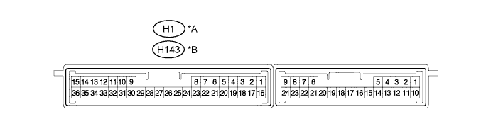
| *A | w/ Entry Function | *B | w/o Entry Function |
Measure the voltage and resistance according to the value(s) in the table below.
| Tester Connection | Wiring Color | Terminal Description | Condition | Specified Condition |
| H1-1 (+B) - H1-15 (E) | B - W-B | Auxiliary battery power supply | Power switch off | 11 to 14 V |
| H1-15 (E) - Body ground | W-B - Body ground | Ground | Always | Below 1 Ω |
| Tester Connection | Wiring Color | Terminal Description | Condition | Specified Condition |
| H143-1 (+B) - H143-15 (E) | B - W-B | Auxiliary battery power supply | Power switch off | 11 to 14 V |
| H143-15 (E) - Body ground | W-B - Body ground | Ground | Always | Below 1 Ω |
Reconnect the H1*1 or H143*2 certification ECU (smart key ECU assembly) connector.
Measure the voltage and check for pulses according to the value(s) in the table below.
| Tester Connection | Wiring Color | Terminal Description | Condition | Specified Condition |
| H1-16 (IG) - H1-15 (E) | BE - W-B | Power switch power supply | Power switch on (IG) | 11 to 14 V |
| H1-16 (IG) - H1-15 (E) | BE - W-B | Power switch power supply | Power switch off | Below 1 V |
| H1-29 (LIN) - H1-15 (E) | B - W-B | LIN communication line | Power switch on (IG) | Pulse generation |
| Tester Connection | Wiring Color | Terminal Description | Condition | Specified Condition |
| H143-16 (IG) - H143-15 (E) | BE - W-B | Power switch power supply | Power switch on (IG) | 11 to 14 V |
| H143-16 (IG) - H143-15 (E) | BE - W-B | Power switch power supply | Power switch off | Below 1 V |
| H143-29 (LIN) - H143-15 (E) | B - W-B | LIN communication line | Power switch on (IG) | Pulse generation |
| CHECK ID CODE BOX (IMMOBILISER CODE ECU) |
Disconnect the H22 ID code box (immobiliser code ECU) connector.

Measure the voltage and resistance according to the value(s) in the table below.
| Tester Connection | Wiring Color | Terminal Description | Condition | Specified Condition |
| H22-1 (+B) - H22-8 (GND) | B - W-B | Auxiliary battery power supply | Power switch off | 11 to 14 V |
| H22-8 (GND) - Body ground | W-B - Body ground | Ground | Always | Below 1 Ω |
Reconnect the H22 ID code box (immobiliser code ECU) connector.
Check for pulses according to the value(s) in the table below.
| Tester Connection | Wiring Color | Terminal Description | Condition | Specified Condition |
| H22-3 (LIN1) - H22-8 (GND) | B - W-B | LIN communication line | Power switch on (IG) | Pulse generation |
| CHECK TRANSMISSION CONTROL ECU ASSEMBLY |
Disconnect the A21 and A22 transmission control ECU assembly connectors.

Measure the voltage and resistance according to the value(s) in the table below.
| Tester Connection | Wiring Color | Terminal Description | Condition | Specified Condition |
| A21-15 (BATT) - Body ground | SB - Body ground | Auxiliary battery power supply | Power switch off | 11 to 14 V |
| A22-1 (E1) - Body ground | BR - Body ground | Ground | Always | Below 1 Ω |
| A22-5 (E02) - Body ground | W-B - Body ground | Ground | Always | Below 1 Ω |
| A22-6 (E01) - Body ground | W-B - Body ground | Ground | Always | Below 1 Ω |
Reconnect the A21 and A22 transmission control ECU assembly connectors.
Check for pulses according to the value(s) in the table below.
| Tester Connection | Wiring Color | Terminal Description | Condition | Specified Condition |
| A22-24 (LIN) - A22-1 (E1) | B - BR | LIN communication line | Power switch on (IG) | Pulse generation |
| CHECK POWER MANAGEMENT CONTROL ECU |
Disconnect the H3 and H4 power management control ECU connectors.
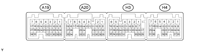
Measure the voltage and resistance according to the value(s) in the table below.
| Tester Connection | Wiring Color | Terminal Description | Condition | Specified Condition |
| H3-1 (AM22) - Body ground | W - Body ground | Auxiliary battery power supply | Power switch off | 11 to 14 V |
| H4-7 (AM21) - Body ground | W - Body ground | Auxiliary battery power supply | Power switch off | 11 to 14 V |
| H3-6 (E1) - Body ground | W-B - Body ground | Ground | Always | Below 1 Ω |
Reconnect the H3 and H4 power management control ECU connectors.
Check for pulses according to the value(s) in the table below.
| Tester Connection | Wiring Color | Terminal Description | Condition | Specified Condition |
| H4-11 (LIN2) - H3-6 (E1) | B - W-B | LIN communication line | Power switch on (IG) | Pulse generation |
| CHECK DOUBLE LOCK DOOR CONTROL RELAY (w/ Double Locking System) |
Disconnect the H140 double lock door control relay assembly connector.

Measure the voltage and resistance according to the value(s) in the table below.
| Tester Connection | Wiring Color | Terminal Description | Condition | Specified Condition |
| H140-1 (+B) - Body ground | R - Body ground | Auxiliary battery power supply | Power switch off | 11 to 14 V |
| H140-7 (CPUB) - Body ground | BR - Body ground | Auxiliary battery power supply | Power switch off | 11 to 14 V |
| H140-14 (GND) - Body ground | W-B - Body ground | Ground | Always | Below 1 Ω |
Reconnect the H140 double lock door control relay assembly connector.
Check for pulses according to the value(s) in the table below.
| Tester Connection | Wiring Color | Terminal Description | Condition | Specified Condition |
| H140-9 (MPX1) - Body ground | P - Body ground | LIN communication line | Double lock unset | Pulse generation |
