DTC B1273 Sliding Roof ECU Communication Stop |
| DTC No. | DTC Detection Condition | Trouble Area |
| B1273 | No communication between sliding roof ECU (sliding roof drive gear assembly) and main body ECU (multiplex network body ECU) for 10 seconds or more. |
|
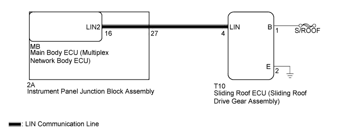
| 1.INSPECT INSTRUMENT PANEL JUNCTION BLOCK ASSEMBLY |
Remove the instrument panel junction block assembly (Click here).
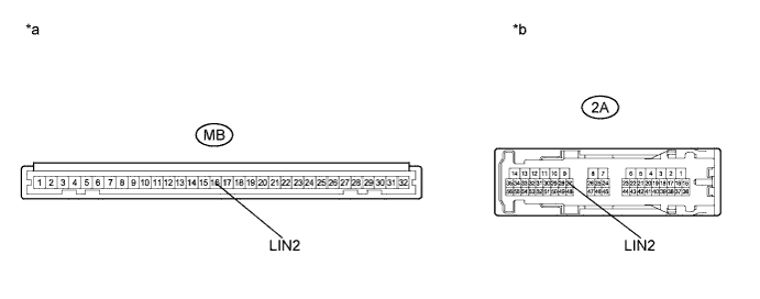
Remove the main body ECU (multiplex network body ECU) from the instrument panel junction block assembly.
Measure the resistance according to the value(s) in the table below.
| Tester Connection | Condition | Specified Condition |
| 2A-27 (LIN2)- MB-16 (LIN2) | Always | Below 1 Ω |
| 2A-27 (LIN2) - Body ground | Always | 10 kΩ or higher |
| *a | Component without harness connected (Instrument Panel Junction Block Assembly) | *b | Component without harness connected (Instrument Panel Junction Block Assembly) |
|
| ||||
| OK | |
 |
| 2.CHECK HARNESS AND CONNECTOR (MAIN BODY ECU - SLIDING ROOF ECU) |
Disconnect the T10 sliding roof ECU (sliding roof drive gear assembly) connector.
Measure the resistance according to the value(s) in the table below.
| Tester Connection | Condition | Specified Condition |
| 2A-27 (LIN2) - T10-4 (LIN) | Always | Below 1 Ω |
| 2A-27 (LIN2) - Body ground | Always | 10 kΩ or higher |
|
| ||||
| OK | |
|
| 3.CHECK HARNESS AND CONNECTOR (SLIDING ROOF ECU - BATTERY, BODY GROUND) |
Measure the voltage according to the value(s) in the table below.
| Tester Connection | Condition | Specified Condition |
| T10-1 (B) - T10-2 (E) | Power switch off | 11 to 14 V |
Measure the resistance according to the value(s) in the table below.
| Tester Connection | Condition | Specified Condition |
| T10-2 (E) - Body ground | Always | 10 kΩ or higher |
|
| ||||
| OK | |
|
| 4.REPLACE SLIDING ROOF ECU (SLIDING ROOF DRIVE GEAR ASSEMBLY) |
Replace the sliding roof ECU (sliding roof drive gear assembly) (Click here).
| NEXT | |
|
| 5.CHECK DTC OUTPUT |
Clear the DTC (Click here).
Recheck for DTCs.
|
| ||||
| OK | ||
 | ||
| ||

