DTC B2786 No Response from Steering Lock ECU |
| DTC No. | DTC Detection Condition | Trouble Area |
| B2786 | No communication between transmission control ECU assembly and certification ECU (smart key ECU assembly) for 10 seconds or more. |
|
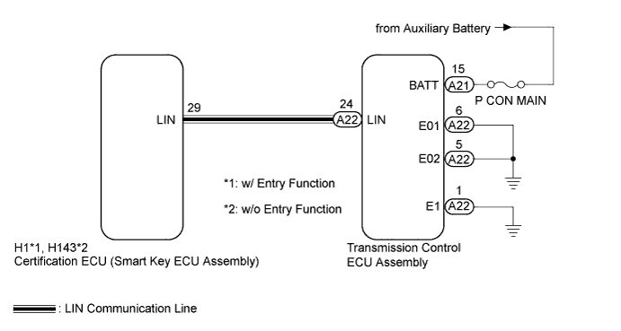
| 1.CHECK HARNESS AND CONNECTOR (TRANSMISSION CONTROL ECU ASSEMBLY - BATTERY AND BODY GROUND) |
Disconnect the A21 and A22 transmission control ECU assembly connectors.
Measure the resistance and voltage according to the value(s) in the table below.
| Tester Connection | Condition | Specified Condition |
| A22-6 (E01) - Body ground | Always | Below 1 Ω |
| A22-5 (E02) - Body ground | Always | Below 1 Ω |
| A22-1 (E1) - Body ground | Always | Below 1 Ω |
| Tester Connection | Condition | Specified Condition |
| A21-15 (BATT) - Body ground | Power switch off | 11 to 14 V |
|
| ||||
| OK | |
 |
| 2.CHECK HARNESS AND CONNECTOR (CERTIFICATION ECU - TRANSMISSION CONTROL ECU ASSEMBLY) |
Disconnect the H1*1 or H143*2 certification ECU (smart key ECU assembly) connector.
Measure the resistance according to the value(s) in the table below.
| Tester Connection | Condition | Specified Condition |
| H1-29 (LIN) - A22-24 (LIN) | Always | Below 1 Ω |
| H1-29 (LIN) - Body ground | Always | 10 kΩ or higher |
| Tester Connection | Condition | Specified Condition |
| H143-29 (LIN) - A22-24 (LIN) | Always | Below 1 Ω |
| H143-29 (LIN) - Body ground | Always | 10 kΩ or higher |
|
| ||||
| OK | |
|
| 3.REPLACE TRANSMISSION CONTROL ECU ASSEMBLY |
Replace the transmission control ECU assembly (Click here).
| NEXT | |
|
| 4.CHECK DTC OUTPUT |
Clear the DTC (Click here).
Recheck for DTCs.
|
| ||||
| OK | ||
 | ||
| ||

