DTC B2325 LIN Communication Bus Malfunction |
| DTC No. | DTC Detection Condition | Trouble Area |
| B2325 | Main body ECU (multiplex network body ECU) detects errors in communication with the ECUs connected to the door bus lines 3 times in a row. |
|
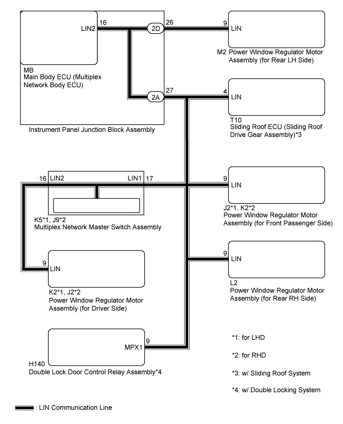
| 1.CHECK HARNESS AND CONNECTOR (POWER WINDOW REGULATOR MOTOR (DRIVER SIDE) - MASTER SWITCH) |
Disconnect the K5*1 or J9*2 multiplex network master switch connector.
Disconnect the K2*1 or J2*2 power window regulator motor (for driver side) connector.
Measure the resistance according to the value(s) in the table below.
| Tester Connection | Condition | Specified Condition |
| K5-16 (LIN2) - K2-9 (LIN)*1 J9-16 (LIN2) - J2-9 (LIN)*2 | Always | Below 1 Ω |
| K5-16 (LIN2) - Body ground*1 J9-16 (LIN2) - Body ground*2 | Always | 10 kΩ or higher |
|
| ||||
| OK | |
 |
| 2.INSPECT MULTIPLEX NETWORK MASTER SWITCH ASSEMBLY |
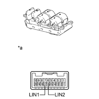 |
Remove the multiplex network master switch assembly (Click here).
Measure the resistance according to the value(s) in the table below.
| Tester Connection | Condition | Specified Condition |
| 16 (LIN2) - 17 (LIN1) | Always | Below 1 Ω |
| 16 (LIN2) - Body ground | Always | 10 kΩ or higher |
| *a | Component without harness connected (Multiplex Network Master Switch Assembly) |
|
| ||||
| OK | |
|
| 3.INSPECT INSTRUMENT PANEL JUNCTION BLOCK ASSEMBLY |
Remove the instrument panel junction block assembly (Click here).
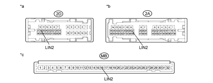
Remove the main body ECU (multiplex network body ECU) from the instrument panel junction block assembly.
Measure the resistance according to the value(s) in the table below.
| Tester Connection | Condition | Specified Condition |
| 2D-26 (LIN2) - MB-16 (LIN2) | Always | Below 1 Ω |
| 2A-27 (LIN2) - MB-16 (LIN2) | Always | Below 1 Ω |
| 2A-27 (LIN2) - Body ground | Always | 10 kΩ or higher |
| *a | Component without harness connected (Instrument Panel Junction Block Assembly) | *b | Component without harness connected (Instrument Panel Junction Block Assembly) |
| *c | Component without harness connected (Instrument Panel Junction Block Assembly) | - | - |
|
| ||||
| OK | |
|
| 4.CHECK HARNESS AND CONNECTOR (INSTRUMENT JUNCTION BLOCK - EACH ECU) |
Disconnect the J2*1, K2*2, H140*3, T10*4, L2 and M2 connectors.
Measure the resistance according to the value(s) in the table below.
| Tester Connection | Condition | Specified Condition |
| 2D-26 (LIN2) - M2-9 (LIN) | Always | Below 1 Ω |
| 2A-27 (LIN2) - L2-9 (LIN) | Always | Below 1 Ω |
| 2A-27 (LIN2) - K5-17 (LIN1)*1 2A-27 (LIN2) - J9-17 (LIN1)*2 | Always | Below 1 Ω |
| 2A-27 (LIN2) - J2-9 (LIN)*1 2A-27 (LIN2) - K2-9 (LIN)*2 | Always | Below 1 Ω |
| 2A-27 (LIN2) - H140-9 (MPX1)*3 | Always | Below 1 Ω |
| 2A-27 (LIN2) - T10-4 (LIN)*4 | Always | Below 1 Ω |
| 2D-26 (LIN2) - Body ground | Always | 10 kΩ or higher |
| 2A-27 (LIN2) - Body ground | Always | 10 kΩ or higher |
|
| ||||
| OK | |
|
| 5.CHECK DTC OUTPUT (POWER WINDOW REGULATOR MOTOR ASSEMBLY (for REAR LH SIDE)) |
Reconnect the K5*1, J9*2, H140*3, 2A, 2D, T10*4, L2, K2 and J2 connectors.
Clear the DTC (Click here).
After 10 seconds have elapsed, check if the trouble occurs again.
Check for DTCs again.
| Result | Proceed to |
| DTC B2325 is output | A |
| DTC B2325 is not output | B |
|
| ||||
| A | |
|
| 6.CHECK DTC OUTPUT (MULTIPLEX NETWORK MASTER SWITCH ASSEMBLY) |
Reconnect the M2 connector.
Disconnect the K5*1 or J9*2 connector.
Clear the DTC (Click here).
After 10 seconds have elapsed, check if the trouble occurs again.
Check for DTCs again.
| Result | Proceed to |
| DTC B2325 is output | A |
| DTC B2325 is not output | B |
|
| ||||
| A | |
|
| 7.CHECK DTC OUTPUT (POWER WINDOW REGULATOR MOTOR ASSEMBLY (for REAR RH SIDE)) |
Reconnect the K5*1 or J9*2 connector.
Disconnect the L2 connector.
Clear the DTC (Click here).
After 10 seconds have elapsed, check if the trouble occurs again.
Check for DTCs again.
| Result | Proceed to |
| DTC B2325 is output | A |
| DTC B2325 is not output | B |
|
| ||||
| A | |
|
| 8.CHECK DTC OUTPUT (POWER WINDOW REGULATOR MOTOR ASSEMBLY (for DRIVER SIDE)) |
Reconnect the L2 connector.
Disconnect the K2*1 or J2*2 connector.
Clear the DTC (Click here).
After 10 seconds have elapsed, check if the trouble occurs again.
Check for DTCs again.
| Result | Proceed to |
| DTC B2325 is output | A |
| DTC B2325 is not output | B |
|
| ||||
| A | |
|
| 9.CHECK DTC OUTPUT (POWER WINDOW REGULATOR MOTOR ASSEMBLY (for FRONT PASSENGER SIDE)) |
Reconnect the K2*1 or J2*2 connector.
Disconnect the J2*1 or K2*2 connector.
Clear the DTC (Click here).
After 10 seconds have elapsed, check if the trouble occurs again.
Check for DTCs again.
| Result | Proceed to |
| DTC B2325 is output (w/ Sliding Roof System) | A |
| DTC B2325 is output (w/ Double Locking System and w/o Sliding Roof System) | B |
| DTC B2325 is output (w/o Double Locking System and w/o Sliding Roof System) | C |
| DTC B2325 is not output | D |
|
| ||||
|
| ||||
|
| ||||
| A | |
|
| 10.CHECK DTC OUTPUT (SLIDING ROOF ECU (SLIDING ROOF DRIVE GEAR ASSEMBLY)) |
Reconnect the J2*1 or K2*2 connector.
Disconnect the T10 connector.
Clear the DTC (Click here).
After 10 seconds have elapsed, check if the trouble occurs again.
Check for DTCs again.
| Result | Proceed to |
| DTC B2325 is output (w/ Double Locking System) | A |
| DTC B2325 is output (w/o Double Locking System) | B |
| DTC B2325 is not output | C |
|
| ||||
|
| ||||
| A | |
|
| 11.CHECK DTC OUTPUT (DOUBLE LOCK DOOR CONTROL RELAY ASSEMBLY) |
w/ Sliding Roof System:
Reconnect the T10 connector.
w/o Sliding Roof System:
Reconnect the J2*1 or K2*2 connector.
Disconnect the H140 connector.
Clear the DTC (Click here).
After 10 seconds have elapsed, check if the trouble occurs again.
Check for DTCs again.
| Result | Proceed to |
| DTC B2325 is output | A |
| DTC B2325 is not output | B |
|
| ||||
| A | ||
 | ||
| ||


