CONDENSER > INSTALLATION

for Preparation Click here


1. INSTALL COOLER CONDENSER ASSEMBLY
  1. Install the cooler condenser assembly to the hybrid radiator assembly with the 4 bolts.
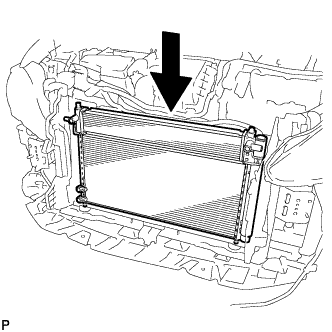
    Torque:
    9.0 N*m{ 92 kgf*cm , 80 in.*lbf }


    E220726
  1. Install the cooler condenser assembly.

    HINT:
    If the condenser is replaced with a new one, add compressor oil to the new condenser.

    Capacity:
    40 cc (1.35 fl. oz.)

    Compressor oil:
    ND-11 or equivalent

    NOTICE:
    Do not use any compressor oil other than ND-OIL 11 or equivalent. If any compressor oil other than ND-OIL 11 or equivalent is used, compressor motor insulation performance may decrease, resulting in a leakage of electric power.


2. INSTALL NO. 2 FAN SHROUD
  1. Install the No. 2 fan shroud with the 2 bolts and 2 claws.

    Torque:
    7.0 N*m{ 71 kgf*cm , 62 in.*lbf }


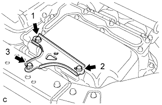
3. INSTALL NO. 1 INVERTER BRACKET


    A248080E01
  1. Temporarily install the No. 1 inverter bracket with the 3 bolts.

  1. Tighten the 3 bolts in the order shown in the illustration.

    Torque:
    14 N*m{ 138 kgf*cm , 10 ft.*lbf }


4. CONNECT NO. 1 INVERTER COOLING HOSE
  1. Using pliers, grip the claws of the clip and slide the clip to connect the No. 1 inverter cooling hose.


5. CONNECT NO. 5 INVERTER COOLING HOSE
  1. Using pliers, grip the claws of the clip and slide the clip to connect the No. 5 inverter cooling hose.


6. CONNECT AIR CONDITIONING TUBE AND ACCESSORY ASSEMBLY
  1. Remove the attached vinyl tape from the pipe and the connecting part of the cooler condenser assembly.

  1. Apply a sufficient amount of compressor oil to a new O-ring and the fitting surface of the pipe joint.

    Compressor oil:
    ND-OIL 11 or equivalent

  1. Install the O-ring to the air conditioning tube and accessory assembly.

    NOTICE:
    1. Keep the O-ring and O-ring fitting surfaces free from dirt or foreign matter.
    2. Do not use any compressor oil other than ND-OIL 11 or equivalent. If any compressor oil other than ND-OIL 11 or equivalent is used, compressor motor insulation performance may decrease, resulting in a leakage of electric power.

  1. Install the air conditioning tube and accessory assembly to the cooler condenser assembly with the bolt.

    Torque:
    5.4 N*m{ 55 kgf*cm , 48 in.*lbf }


7. CONNECT COOLER REFRIGERANT DISCHARGE HOSE
  1. Remove the attached vinyl tape from the hose and the connecting part of the cooler condenser assembly.

  1. Apply a sufficient amount of compressor oil to a new O-ring and the fitting surface of the hose joint.

    Compressor oil:
    ND-OIL 11 or equivalent

  1. Install the O-ring to the cooler refrigerant discharge hose.

    NOTICE:
    1. Keep the O-ring and O-ring fitting surfaces free from dirt or foreign matter.
    2. Do not use any compressor oil other than ND-OIL 11 or equivalent. If any compressor oil other than ND-OIL 11 or equivalent is used, compressor motor insulation performance may decrease, resulting in a leakage of electric power.

  1. Install the cooler refrigerant discharge hose to the cooler condenser assembly with the bolt.

    Torque:
    5.4 N*m{ 55 kgf*cm , 48 in.*lbf }


8. INSTALL HOOD LOCK SUPPORT SUB-ASSEMBLY
  1. Install the hood lock support sub-assembly with the 4 bolts.

    Torque:
    13 N*m{ 133 kgf*cm , 10 ft.*lbf }

  1. Install the No. 2 water by-pass hose to the hood lock support sub-assembly with the bolt.

    Torque:
    19 N*m{ 194 kgf*cm , 14 ft.*lbf }


9. INSTALL HIGH PITCHED HORN ASSEMBLY
  1. Install the high pitched horn assembly with the bolt.

    Torque:
    19 N*m{ 195 kgf*cm , 14 ft.*lbf }

  1. Connect the connector.


10. INSTALL LOW PITCHED HORN ASSEMBLY
  1. Install the low pitched horn assembly with the bolt.

    Torque:
    19 N*m{ 195 kgf*cm , 14 ft.*lbf }

  1. Connect the connector.


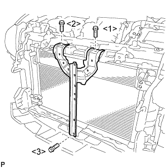
11. INSTALL COOL AIR INTAKE DUCT RETAINER SUB-ASSEMBLY


    E220720E01
  1. Install the cool air intake duct retainer sub-assembly with the 3 bolts.

    Torque:
    6.2 N*m{ 63 kgf*cm , 55 in.*lbf }

    NOTICE:
    Tighten the bolts in the order shown in the illustration to install the cool air intake duct retainer sub-assembly.


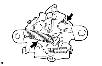
12. INSTALL HOOD LOCK ASSEMBLY (w/o Engine Hood Courtesy Switch)


    B270692
  1. Apply MP grease to the sliding areas of the lock.

  1. Connect the hood lock control cable.

  1. Install the hood lock assembly with the 2 bolts and hood lock bolt.

    Torque:
    8.0 N*m{ 82 kgf*cm , 71 in.*lbf }

  1. Install a new hood lock nut cap.


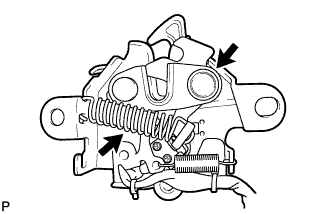
13. INSTALL HOOD LOCK ASSEMBLY (w/ Engine Hood Courtesy Switch)


    B270693
  1. Apply MP grease to the sliding areas of the lock.

  1. Connect the hood lock control cable.

  1. Install the hood lock assembly with the 2 bolts and hood lock bolt.

    Torque:
    8.0 N*m{ 82 kgf*cm , 71 in.*lbf }

  1. Install a new hood lock nut cap.

  1. Engage the clamp.

  1. Connect the connector.


14. INSTALL MILLIMETER WAVE RADAR SENSOR ASSEMBLY (w/ Dynamic Radar Cruise Control System)


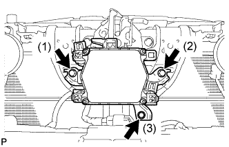
    E214951E01
  1. Tighten the 3 bolts on the millimeter wave radar sensor assembly.

    Torque:
    5.5 N*m{ 56 kgf*cm , 49 in.*lbf }

    HINT:
    Tighten the bolts in the order indicated in the illustration.

  1. Connect the connector.


15. INSTALL FRONT BUMPER ASSEMBLY
(Click here)


16. CONNECT CABLE TO NEGATIVE BATTERY TERMINAL

NOTICE:
When disconnecting the cable, some systems need to be initialized after the cable is reconnected (Click here).


17. INSTALL REAR FLOOR BOARD UPPER NO. 3 PLATE
  1. Engage the 4 claws and 2 guides to install the rear floor board upper No. 3 plate.


18. INSTALL DECK FLOOR BOX RH
  1. Engage the 6 guides.

  1. Install the deck floor box RH with the clip.


19. INSTALL REAR NO. 3 FLOOR BOARD
  1. Install the rear No. 3 floor board.


20. INSTALL REAR DECK FLOOR BOX
  1. Install the rear deck floor box.


21. INSTALL REAR NO. 2 FLOOR BOARD
  1. Install the rear No. 2 floor board.


22. CHARGE AIR CONDITIONING SYSTEM WITH REFRIGERANT
  1. Perform vacuum purging using a vacuum pump or appropriate equipment.


  1. Charge the air conditioning system with refrigerant.
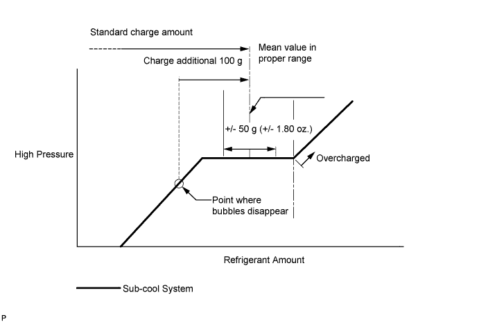
    Refrigerant type:
    HFC-134a (R134a)


    E143108E09

    Standard charge amount:
    470 g (16.6 oz.)

    SST
    09985-20010   (09985-02010, 09985-02050, 09985-02060, 09985-02070, 09985-02080, 09985-02090, 09985-02110, 09985-02130, 09985-02140, 09985-02150)

    NOTICE:
    1. Do not turn the A/C switch on before charging the air conditioning system with refrigerant. Doing so may cause the compressor to work without refrigerant, resulting in overheating of the compressor.
    2. The refrigerant amount should be checked by quantity (weight).
    3. The graph above is shown for reference only. This vehicle is not equipped with a sight glass.
    4. If at all possible, avoid using a manifold gauge set or recovery and recycling unit that has been used for vehicles with conventional compressor oil (ND-OIL 8 or equivalent). If either of these is used, conventional compressor oil remaining in the equipment will enter the air conditioning system of the vehicle, resulting in electrical insulation performance deterioration. A manifold gauge set that has been used 3 times or less can be used if an appropriate one is not available.

    HINT:
    Ensure that sufficient refrigerant is available to recharge the system when using a refrigerant recovery unit. Refrigerant recovery units are not always able to recover 100% of the refrigerant from an air conditioning system.


23. ADD COOLANT (for Inverter)

NOTICE:
  1. Do not reuse the drained coolant because it may contain foreign objects.
  2. If the vehicle is driven with air in the inverter cooling system, damage may occur and the following DTCs may be stored.

    DTC No.
    Detection Item
    P0A01-726
    Motor Electronics Coolant Temperature Sensor Circuit Range / Performance
    P0A04-725
    Motor Electronics Coolant Temperature Sensor Circuit Intermittent
    P0A08-264
    DC / DC Converter Status Circuit
    P0A78-284
    Drive Motor "A" Inverter Performance
    P0A78-286
    Drive Motor "A" Inverter Performance
    P0A7A-322
    Generator Inverter Performance
    P0A7A-324
    Generator Inverter Performance
    P0A93-346
    Inverter Cooling System Performance
    P0A94-553
    DC / DC Converter Performance
    P0A94-557
    DC / DC Converter Performance
    P0AEE-277
    Motor Inverter Temperature Sensor "A" Circuit Range / Performance
    P0AF1-276
    Drive Motor Inverter Temperature Sensor "A" Circuit Intermittent / Erratic
    P0BCD-315
    Generator Inverter Temperature Sensor Circuit Range / Performance
    P0BD0-314
    Generator Inverter Temperature Sensor Circuit Intermittent / Erratic
    P0C39-626
    DC / DC Converter Temperature Sensor "A" Range / Performance
    P0C3C-625
    DC / DC Converter Temperature Sensor "A" Intermittent / Erratic
    P0C3E-628
    DC / DC Converter Temperature Sensor "B" Range / Performance
    P0C41-627
    DC / DC Converter Temperature Sensor "B" Intermittent / Erratic
    P0C73-776
    Motor Electronics Coolant Pump "A" Control Performance


    A248471
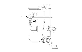
  1. Slowly pour coolant into the reserve tank until it reaches the full line.

    Coolant quantity:
    2.1 liters (2.2 US qts, 1.8 Imp. qts.)

  1. When using the intelligent tester:

    1. Connect the intelligent tester to the DLC3.

    2. Turn the power switch on (IG).

    3. Enter the following menus: Powertrain / Hybrid Control / Active Test / Activate the Water Pump.

    4. Keep the coolant at the full line in the reserve tank to compensate for the drop in coolant level when the air bleeds.

      Standard:
      Air bleeding from the inverter cooling system is completed when the noise made by the inverter water pump assembly becomes smaller and the circulation of coolant in the reserve tank improves.

      HINT:
      Loud noise made by the inverter water pump assembly and poor circulation of coolant in the reserve tank indicates that there is air in the cooling system.

  1. When not using the intelligent tester:

    1. Turn the power switch on (READY). [*1]

    2. Turn the power switch off and add coolant to the full line because the coolant level drops as the air bleeds. [*2]

      NOTICE:
      1. Be sure to turn the power switch off before adding SLLC.
      2. Do not work on the components in the engine compartment while the vehicle is in the READY-on state because the engine is in intermittent operation.

    3. Repeat steps [*1] and [*2] until air bleeding from the cooling system is completed.

      Standard:
      Air bleeding from the inverter cooling system is completed when the noise made by the inverter water pump assembly becomes smaller and the circulation of coolant in the reserve tank improves.

      HINT:
      Loud noise made by the inverter water pump assembly and poor circulation of coolant in the reserve tank indicates that there is air in the cooling system.

  1. After the air is completely bled from the cooling system, tighten the reserve tank cap.


    A248471
  1. Add coolant to the full line of the reserve tank.


24. INSPECT FOR COOLANT LEAK (for Inverter)
  1. Remove the reserve tank cap.

    CAUTION:
    To avoid the danger of being burned, do not remove the reserve tank cap while the coolant for the inverter is still hot.


    A248084
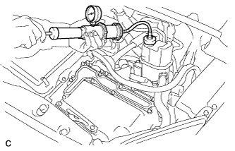
  1. Install a radiator cap tester.

  1. Pump the radiator cap tester to 122 kPa (1.2 kgf/ cm2, 18 psi), and then check that the pressure does not drop.

    HINT:
    If the pressure drops, check the hoses, radiator, inverter water pump assembly, inverter with converter, and hybrid vehicle transaxle assembly for leaks.

  1. Reinstall the reserve tank cap.


25. WARM UP COMPRESSOR
  1. Keep the A/C switch on for at least 2 minutes to warm up the compressor.

    NOTICE:
    To prevent damage to the compressor, be sure to warm up the compressor when turning the air conditioning on after removing and installing air conditioning system lines (including the compressor).


26. INSPECT FOR REFRIGERANT LEAK
  1. After recharging the air conditioning system with refrigerant, inspect for refrigerant leaks using a halogen leak detector.

  1. Carry out the test under the following conditions:
    1. Power switch off.
    2. Secure good ventilation (the halogen leak detector may react to volatile gases which are not refrigerant, such as gasoline vapor and exhaust gas).
    3. Repeat the inspection 2 or 3 times.
    4. Measure the pressure to make sure that there is some refrigerant remaining in the air conditioning system.
      Pressure when the compressor is off: approx. 392 to 588 kPa (3.9 to 5.9 kgf/cm2, 57 to 85 psi)


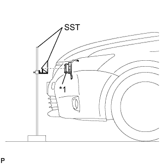
    I042222E40
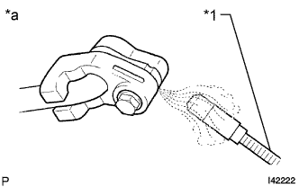
  1. Using a halogen leak detector, inspect for refrigerant leaks from the air conditioning system.
    Text in Illustration 
    *1
    Halogen Leak Detector
    *a
    Inspect for Leak


    N014519E08
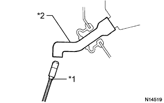
  1. Bring the halogen leak detector close to the drain hose with the detector power off, and then turn the detector on.
    Text in Illustration 
    *1
    Halogen Leak Detector
    *2
    Drain Hose

    HINT:
    1. After the blower motor has stopped, leave the cooling unit for more than 15 minutes.
    2. Bring the halogen leak detector sensor under the drain hose.
    3. When bringing the halogen leak detector close to the drain hose, make sure that the halogen leak detector does not react to volatile gases. If it is not possible to avoid interference from volatile gases, the vehicle should be lifted up to allow checking for leaks.

  1. If a refrigerant leak is not detected from the drain hose, remove the blower motor control from the cooling unit. Insert the halogen leak detector sensor into the unit and check for a leak.

  1. Disconnect the pressure sensor connector and leave it for approximately 20 minutes. Bring the halogen leak detector close to the pressure sensor and check for a leak.

    HINT:
    When checking for leaks, the presence of oily dirt at a joint can indicate a leak.


27. ADJUST HOOD SUB-ASSEMBLY
(Click here)


28. ADJUST MILLIMETER WAVE RADAR SENSOR ASSEMBLY (w/ Dynamic Radar Cruise Control System)


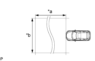
E219881E01
Text in Illustration 
*a
Approx. 10 m
*b
Approx. 14 m

CAUTION:
Radio frequency radiation exposure information:
  1. This equipment should be kept with minimum distance of 20 cm (7.87 in.) between the radiator (antenna) and your body at all times during adjustment.
  2. This transmitter must not be co-located or operating in conjunction with any other antenna or transmitter.

NOTICE:
  1. Perform measurements on a level surface.
  2. Make sure that no large pieces of metal are within a 10 m (32.8 ft.) x 14 m (45.9 ft.) area in front of the vehicle. If possible, the surrounding area should also be free of large metal objects.

  1. Before adjusting the radar beam axis, prepare the vehicle as follows.

    1. Check the tire pressure and adjust it if necessary.

    2. Remove all excess weight from the vehicle (luggage, heavy objects, etc.).

    3. Remove the radiator support opening cover (Click here).
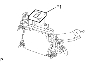


    E214952E01
  1. Check and adjust the vertical direction of the radar sensor.
    Text in Illustration 
    *1
    Level

    1. Remove dust, oil and foreign matter from the radar sensor's level rack.

    2. Set a level on the radar sensor's level rack.
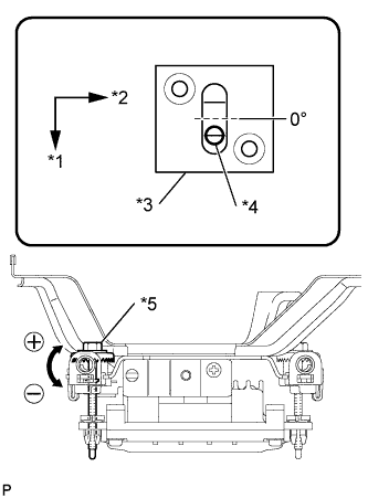


    3. E219867E01
    4. Check that the level's air bubble is within the red frame.
      Text in Illustration 
      *1
      Vehicle Front
      *2
      LH
      *3
      Level
      *4
      Air Bubble
      *5
      Bolt A

      OK:
      Level's air bubble is within red frame.

      If the bubble is not within the red frame, use a screwdriver to adjust bolt A until the air bubble is within the red frame.

      HINT:
      1. The adjustable range within the level's red frame is +/- 0.2°.
      2. The target angle is +0.2° (upward angle of 0.2°).

        Adjustment:
        Adjustment Direction
        Adjustment Procedure
        Adjustment Angle
        Vertical adjustment
        Upward direction: Turn screwdriver to negative (-) side
        When screwdriver is turned once, adjustment changes by about 0.12°.
        Downward direction: Turn screwdriver to positive (+) side


    E219868E01
  1. Adjust the reflector height.
    Text in Illustration 
    *1
    Millimeter Wave Radar Sensor

    1. Adjust the reflector so that the center of SST reflector is the same height as the millimeter wave radar sensor or the center of emblem.
      SST
      09870-60000   (09870-60010)
      09870-60040  

      HINT:
      Prepare a 10 m (32.8 ft.) string, a string with a sharp-pointed weight (plumb bob), and a 5 m (16.4 ft.) tape measure.


    E219872E01
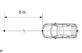
  1. Place the reflector.

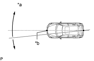
    1. Hang the string (with weight) from the center of the vehicle's rear emblem. Mark the vehicle's rear center point on the ground. Repeat for the front of the vehicle.


    2. E219883E01
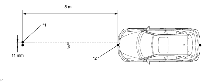
    3. Set one end of the 10 m (32.8 ft.) string on the vehicle's rear center point. Run the string over the vehicle's front center point to a position 5 m (16.4 ft.) beyond the vehicle's front center point, as shown in the illustration. Mark the 5 m (16.4 ft.) position.
      Text in Illustration 
      *a
      Adjust center by moving string to right and left
      *b
      Extend string through front center mark


    4. Using a tape measure, measure 11 mm (0.433 in.) to the right of the 5 m (16.4 ft.) position. Place the reflector at that position.
      NOTICE:
      Perform the operation as precisely as possible.


      E219870E01


      Text in Illustration 
      *1
      Reflector Placement Point
      *2
      Millimeter Wave Radar Sensor Position

  1. Check the radar beam axis.

    HINT:
    If a screen indicating an error is displayed while performing this procedure, perform the procedure again from *1.


    1. Connect the intelligent tester to the DLC3.

    2. Turn the power switch on (IG).

    3. Turn the intelligent tester on, and turn the cruise control main switch on.

    4. Select "Auto" from the intelligent tester display screen.*1

    5. Select "Radar Cruise" from the display screen.

    6. Select "Utility" from the display screen.

    7. Select "Beam Axis Adjustment" from the display screen.

    8. Follow the tester display, and select "Next".

      CAUTION:
      Do not come within 20 cm (7.87 in.) of the radar sensor.

      NOTICE:
      1. Turn the cruise control main switch on before pressing Next.
      2. Make sure that there is at least 20 cm (7.87 in.) between the radar sensor and any nearby individuals.

    9. Check the following items on the radar cruise divergence data screen.

      NOTICE:
      While using the intelligent tester's beam axis adjustment mode, the actual direction and angle of the radar sensor may be different from the intelligent tester's data. In such a case, the deviation is displayed on the combination meter's multi-information display.

      1. Confirm that the distance value is approximately 5 m (16.4 ft.).

        HINT:
        1. A value between 0.0 m (0.0 ft.) and 6.3 m (20.7 ft.) is indicated.
        2. If the distance is 0.0 m (0.0 ft.), the sensor cannot detect the target. Reconfirm that there is no metal in the specified area in front of the vehicle (refer to the notice at the beginning of this adjustment procedure).

      2. Confirm that the left/right side value is between 0.0 m (0.0 ft.) and 6.3 m (20.7 ft.).

        HINT:
        If the distance is 0.0 m (0.0 ft.), the sensor cannot detect the target. Reconfirm that there is no metal in the specified area in front of the vehicle (refer to the notice at the beginning of this adjustment procedure).


  1. Check and adjust the horizontal direction of the radar sensor.

    1. Check that the divergence of the radar beam axis is 0°.
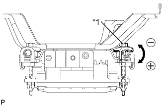
      Standard:
      0° (Both right and left)

      If the axis is not as specified, use a screwdriver to adjust bolt B until the divergence of the radar beam axis is 0°.


    2. E219871E01
    3. Based on the measured divergence of the beam axis, turn and adjust bolt B for horizontal adjustment of the millimeter wave radar sensor using a screwdriver.
      Text in Illustration 
      *1
      Bolt B

      Adjustment:
      Adjustment Direction
      Adjustment Procedure
      Adjustment Angle
      Horizontal adjustment
      Right direction: Turn screwdriver to positive (+) side.
      When screwdriver is turned once, adjustment changes by about 0.07°.
      Left direction: Turn screwdriver to negative (-) side.

      HINT:
      If the value does not change to 0°, it is possible that the sensor is aiming at something different. Reconfirm that there are no reflective materials in the surrounding area.

    4. Select "Next". The driving learning value is automatically reset.

      HINT:
      A buzzer will sound for 10 seconds or more.

    5. Disconnect the intelligent tester from the DLC3.


  1. Recheck and readjust the vertical direction of the radar sensor.


      E214952E01
    1. Set a level on the radar sensor's level rack.
      Text in Illustration 
      *1
      Level


    2. E219867E01
    3. Check that the level's air bubble is within the red frame.
      Text in Illustration 
      *1
      Vehicle Front
      *2
      LH
      *3
      Level
      *4
      Air Bubble
      *5
      Bolt A

      OK:
      Level's air bubble is within the red frame.

      If the bubble is not within the red frame, use a screwdriver to adjust bolt A until the level's air bubble is within the red frame.

      HINT:
      1. The adjustable range within the red frame is +/- 0.2°.
      2. The target angle is +0.2° (upward angle of 0.2°).

        Adjustment:
        Adjustment Direction
        Adjustment Procedure
        Adjustment Angle
        Vertical adjustment
        Upward direction: Turn screwdriver to negative (-) side
        When screwdriver is turned once, adjustment changes by about 0.12°.
        Downward direction: Turn screwdriver to positive (+) side

  1. After adjusting the radar beam axis, return the vehicle to its original condition.

    1. If any heavy items were removed from the vehicle, return them (luggage, heavy objects, etc.).

    2. Install the radiator support opening cover (Click here).