ENGINE UNIT > INSPECTION |
| 1. INSPECT NO. 1 VALVE ROCKER ARM SUB-ASSEMBLY |
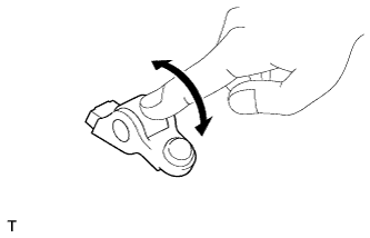 |
Turn the roller by hand to check that it turns smoothly.
If the roller does not turn smoothly, replace the No. 1 valve rocker arm sub-assembly.
| 2. INSPECT VALVE LASH ADJUSTER ASSEMBLY |
Place the lash adjuster into a container filled with new engine oil.
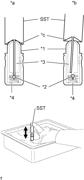 |
Insert the tip of SST into the lash adjuster plunger and use the tip to press down on the check ball inside the plunger.
| *1 | Plunger |
| *2 | Check Ball |
| *3 | Low Pressure Chamber |
| *4 | High Pressure Chamber |
| *a | CORRECT |
| *b | INCORRECT |
| *c | Taper Part |
Squeeze SST and the valve lash adjuster together to move the plunger up and down 5 to 6 times.
Check the movement of the plunger and bleed the air.
After bleeding the air, remove SST. Then try to quickly and firmly press the plunger with your fingers.
| 3. INSPECT CHAIN SUB-ASSEMBLY |
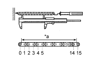 |
Pull the chain with a force of 147 N (15 kgf, 33.0 lbf) as shown in the illustration.
| *a | Measurement Length |
Using a vernier caliper, measure the length of 15 links.
| 4. INSPECT NO. 2 CHAIN SUB-ASSEMBLY |
|
Pull the chain with a force of 147 N (15 kgf, 33.0 lbf) as shown in the illustration.
| *a | Measurement Length |
Using a vernier caliper, measure the length of 15 links.
| 5. INSPECT OIL PUMP DRIVE GEAR |
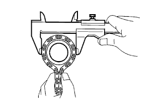 |
Place the chain around the oil pump drive gear.
Using a vernier caliper, measure the diameter of the oil pump drive gear and chain.
| 6. INSPECT OIL PUMP DRIVE SHAFT GEAR |
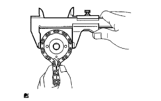 |
Place the chain around the oil pump drive shaft gear.
Using a vernier caliper, measure the diameter of the oil pump drive shaft gear and chain.
| 7. INSPECT CAMSHAFT TIMING GEAR ASSEMBLY |
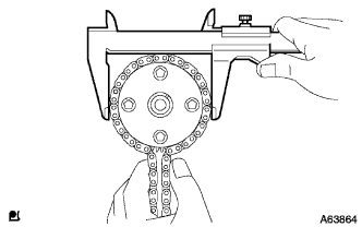 |
Place the chain around the camshaft timing gear assembly.
Using a vernier caliper, measure the diameter of the camshaft timing gear assembly and chain.
| 8. INSPECT CAMSHAFT TIMING SPROCKET |
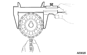 |
Place the chain around the camshaft timing sprocket.
Using a vernier caliper, measure the diameter of the camshaft timing sprocket and chain.
| 9. INSPECT CRANKSHAFT TIMING GEAR |
|
Place the chain around the crankshaft timing gear.
Using a vernier caliper, measure the diameter of the crankshaft timing gear and chain.
| 10. INSPECT CHAIN TENSIONER SLIPPER |
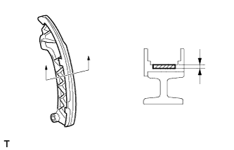 |
Using a vernier caliper, measure the chain tensioner slipper wear.
| 11. INSPECT NO. 1 CHAIN VIBRATION DAMPER |
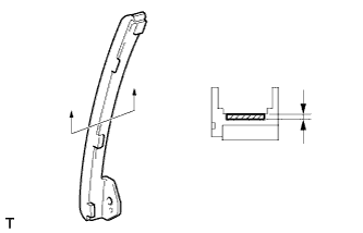 |
Using a vernier caliper, measure the No. 1 chain vibration damper wear.
| 12. INSPECT NO. 2 CHAIN VIBRATION DAMPER |
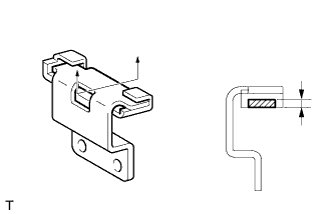 |
Using a vernier caliper, measure the No. 2 chain vibration damper wear.
| 13. INSPECT CHAIN TENSIONER PLATE |
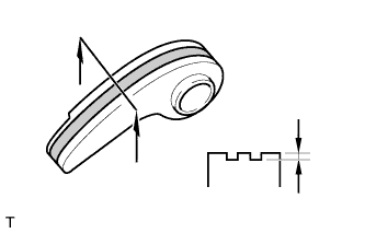 |
Using a vernier caliper, measure the chain tensioner plate wear.
| 14. INSPECT NO. 1 CHAIN TENSIONER |
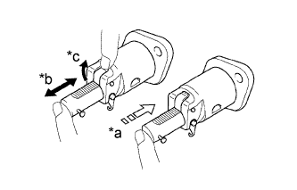 |
Check that the plunger moves smoothly when the cam is raised with your finger.
| *a | Lock |
| *b | Move |
| *c | Raise |
Release the cam, then check that the plunger is locked in place by the cam and does not move when pushing with your finger.
If necessary, replace the No. 1 chain tensioner.
| 15. INSPECT CAMSHAFT |
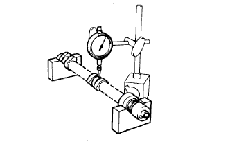 |
Inspect the camshaft for runout.
Place the camshaft on V-blocks.
Using a dial indicator, measure the circle runout at the center journal.
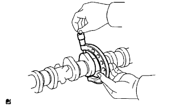 |
Inspect the cam lobes.
Using a micrometer, measure the cam lobe height.
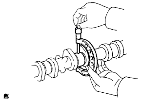 |
Inspect the camshaft journals.
Using a micrometer, measure the journal diameter.
| Journal Position | Specified Condition |
| No. 1 | 34.449 to 34.465 mm (1.3563 to 1.3569 in.) |
| Others | 22.949 to 22.965 mm (0.90350 to 0.90413 in.) |
| 16. INSPECT NO. 2 CAMSHAFT |
|
Inspect the No. 2 camshaft for runout.
Place the No. 2 camshaft on V-blocks.
Using a dial indicator, measure the circle runout at the center journal.
|
Inspect the cam lobes.
Using a micrometer, measure the cam lobe height.
|
Inspect the camshaft journals.
Using a micrometer, measure the journal diameter.
| Journal Position | Specified Condition |
| No. 1 | 34.449 to 34.465 mm (1.3563 to 1.3569 in.) |
| Others | 22.949 to 22.965 mm (0.90350 to 0.90413 in.) |
| 17. INSPECT CYLINDER HEAD SET BOLT |
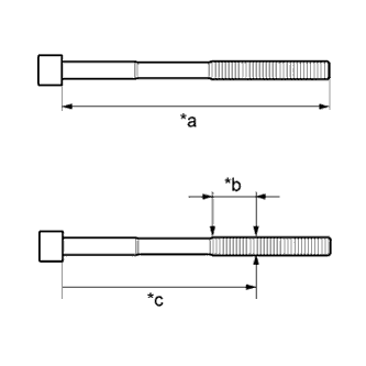 |
Using a vernier caliper, measure the length of the cylinder head set bolt from the seat to the end.
| *a | Measurement Length |
| *b | Measurement Area |
| *c | Distance |
Using a vernier caliper, measure the diameter of the threaded portion of the bolt at its thinnest point.
| 18. INSPECT EXHAUST MANIFOLD |
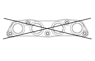 |
Using a precision straightedge and feeler gauge, measure the warpage on the surface that contacts the cylinder head.
