POWER MIRROR CONTROL SYSTEM (w/ Memory) > Driver Side Power Mirror cannot be Adjusted with Power Mirror Switch |
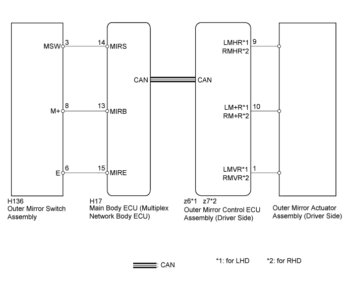
| 1.CHECK CAN COMMUNICATION SYSTEM |
Check for CAN communication system DTCs (Click here).
|
| ||||
| OK | |
 |
| 2.READ VALUE USING INTELLIGENT TESTER (OUTER MIRROR SWITCH ASSEMBLY) |
Connect the intelligent tester to the DLC3.
Turn the power switch on (IG).
Turn the intelligent tester on.
Enter the following menus: Body / Main Body / Data List.
Read the Data List according to the display on the intelligent tester.
| Tester Display | Measurement Item/Range | Normal Condition | Diagnostic Note |
| Mirror Selection SW (L) | Mirror select switch signal for LH mirror / ON or OFF | ON: Mirror select switch in L position OFF: Mirror select switch off or in R position | *1 |
| Mirror Selection SW (R) | Mirror select switch signal for RH mirror / ON or OFF | ON: Mirror select switch in R position OFF: Mirror select switch off or in L position | *2 |
| Mirror Position SW (R) | Mirror adjust switch signal (Right) / ON or OFF | ON: Mirror adjust switch pressed right OFF: Mirror adjust switch not pressed right | Check with the mirror select switch in the L position.*1 Check with the mirror select switch in the R position.*2 |
| Mirror Position SW (L) | Mirror adjust switch signal (Left) / ON or OFF | ON: Mirror adjust switch pressed left OFF: Mirror adjust switch not pressed left | Check with the mirror select switch in the L position.*1 Check with the mirror select switch in the R position.*2 |
| Mirror Position SW (Up) | Mirror adjust switch signal (Up) / ON or OFF | ON: Mirror adjust switch pressed up OFF: Mirror adjust switch not pressed up | Check with the mirror select switch in the L position.*1 Check with the mirror select switch in the R position.*2 |
| Mirror Position SW (Dwn) | Mirror adjust switch signal (Down) / ON or OFF | ON: Mirror adjust switch pressed down OFF: Mirror adjust switch not pressed down | Check with the mirror select switch in the L position.*1 Check with the mirror select switch in the R position.*2 |
|
| ||||
| OK | |
|
| 3.PERFORM ACTIVE TEST USING INTELLIGENT TESTER (POWER MIRROR CONTROL FUNCTION) |
Enter the following menus: Body / Mirror L*1 or Mirror R*2 / Active Test.
Perform the Active Test according to the display on the intelligent tester.
| Tester Display | Test Part | Control Range | Diagnostic Note |
| Mirror Up/Down | Mirror vertical operation | Up / Down |
|
| Mirror Right/Left | Mirror horizontal operation | Right / Left |
|
|
| ||||
| OK | ||
 | ||
| ||
| 4.INSPECT OUTER MIRROR ACTUATOR ASSEMBLY (DRIVER SIDE) |
for LHD:
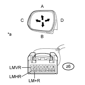 |
Remove the outer rear view mirror assembly LH (Click here).
Apply auxiliary battery voltage and check the operation of the outer rear view mirror assembly LH.
| Measurement Condition | Specified Condition |
| Auxiliary battery positive (+) → Terminal z6-1 (LMVR) Auxiliary battery negative (-) → Terminal z6-10 (LM+R) | Turns upward |
| Auxiliary battery negative (-) → Terminal z6-1 (LMVR) Auxiliary battery positive (+) → Terminal z6-10 (LM+R) | Turns downward |
| Auxiliary battery positive (+) → Terminal z6-9 (LMHR) Auxiliary battery negative (-) → Terminal z6-10 (LM+R) | Turns left |
| Auxiliary battery negative (-) → Terminal z6-9 (LMHR) Auxiliary battery positive (+) → Terminal z6-10 (LM+R) | Turns right |
| *a | Component without harness connected (Outer Mirror Actuator Assembly LH) |
for RHD:
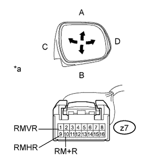 |
Remove the outer rear view mirror assembly RH (Click here).
Apply auxiliary battery voltage and check the operation of the outer rear view mirror assembly RH.
| Measurement Condition | Specified Condition |
| Auxiliary battery positive (+) → Terminal z7-1 (RMVR) Auxiliary battery negative (-) → Terminal z7-10 (RM+R) | Turns upward |
| Auxiliary battery negative (-) → Terminal z7-1 (RMVR) Auxiliary battery positive (+) → Terminal z7-10 (RM+R) | Turns downward |
| Auxiliary battery positive (+) → Terminal z7-9 (RMHR) Auxiliary battery negative (-) → Terminal z7-10 (RM+R) | Turns left |
| Auxiliary battery negative (-) → Terminal z7-9 (RMHR) Auxiliary battery positive (+) → Terminal z7-10 (RM+R) | Turns right |
| *a | Component without harness connected (Outer Mirror Actuator Assembly RH) |
|
| ||||
| OK | ||
| ||
| ||
| 5.INSPECT OUTER MIRROR SWITCH ASSEMBLY |
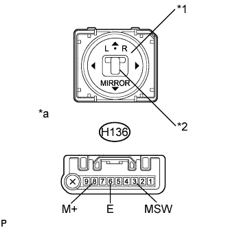 |
Remove the outer mirror switch assembly (Click here).
Measure the resistance according to the value(s) in the table below.
| Tester Connection | Switch Condition | Specified Condition |
| H136-8 (M+) - H136-6 (E) | Mirror adjust switch pressed up | 90 to 110 Ω |
| Mirror adjust switch pressed down | 437 to 503 Ω | |
| Mirror adjust switch pressed left | 744 to 856 Ω | |
| Mirror adjust switch pressed right | 225 to 275 Ω | |
| H136-3 (MSW) - H136-6 (E) | Mirror select switch L | 90 to 110 Ω |
| Mirror select switch R | Below 10 Ω | |
| Mirror select switch off | 10 kΩ or higher |
| *1 | Mirror Adjust Switch |
| *2 | Mirror Select Switch |
| *a | Component without harness connected (Outer Mirror Switch Assembly) |
|
| ||||
| OK | |
|
| 6.CHECK HARNESS AND CONNECTOR (OUTER MIRROR SWITCH - MAIN BODY ECU) |
Disconnect the H136 connector from the outer mirror switch assembly.
Disconnect the H17 connector from the main body ECU (multiplex network body ECU).
Measure the resistance according to the value(s) in the table below.
| Tester Connection | Condition | Specified Condition |
| H136-6 (E) - H17-15 (MIRE) | Always | Below 1 Ω |
| H136-8 (M+) - H17-13 (MIRB) | Always | Below 1 Ω |
| H136-3 (MSW) - H17-14 (MIRS) | Always | Below 1 Ω |
| H136-6 (E) - Body ground | Always | 10 kΩ or higher |
| H136-8 (M+) - Body ground | Always | 10 kΩ or higher |
| H136-3 (MSW) - Body ground | Always | 10 kΩ or higher |
|
| ||||
| OK | ||
| ||
| ||


