AIR CONDITIONING SYSTEM > PTC Heater Circuit |
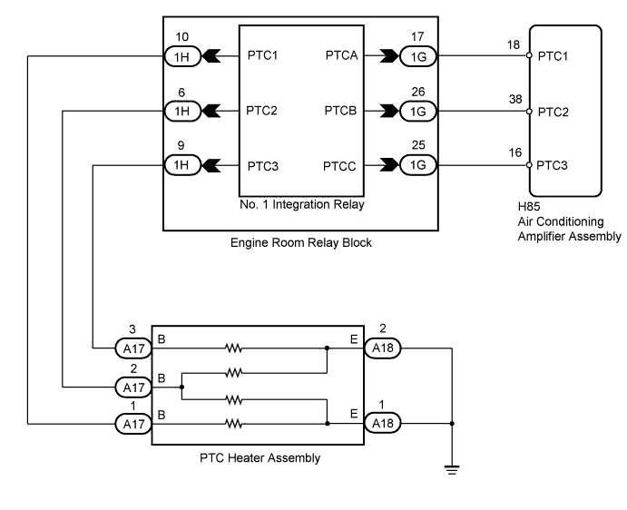
| 1.INSPECT PTC HEATER ASSEMBLY |
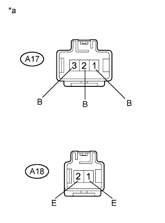 |
Remove the PTC heater assembly.
Measure the resistance according to the value(s) in the table below.
| Tester Connection | Condition | Specified Condition |
| A17-3 (B) - A18-2 (E) | Always | Below 1 Ω |
| A17-2 (B) - A18-2 (E) | Always | Below 1 Ω |
| A17-2 (B) - A18-1 (E) | Always | Below 1 Ω |
| A17-1 (B) - A18-1 (E) | Always | Below 1 Ω |
| *a | Component without harness connected (PTC Heater Assembly) |
|
| ||||
| OK | |
 |
| 2.CHECK HARNESS AND CONNECTOR (PTC HEATER ASSEMBLY - BODY GROUND) |
Measure the resistance according to the value(s) in the table below.
| Tester Connection | Condition | Specified Condition |
| A18-1 (E) - Body ground | Always | Below 1 Ω |
| A18-2 (E) - Body ground | Always | Below 1 Ω |
|
| ||||
| OK | |
|
| 3.CHECK HARNESS AND CONNECTOR (PTC HEATER ASSEMBLY - NO. 1 INTEGRATION RELAY) |
Disconnect the PTC heater assembly connector.
Disconnect the engine room relay block and junction block (No. 1 integration relay) connector.
Measure the resistance according to the value(s) in the table below.
| Tester Connection | Condition | Specified Condition |
| A17-1 (B) - 1H-10 (PTC1) | Always | Below 1 Ω |
| A17-2 (B) - 1H-6 (PTC2) | Always | Below 1 Ω |
| A17-3 (B) - 1H-9 (PTC3) | Always | Below 1 Ω |
| A17-1 (B) - Body ground | Always | 10 kΩ or higher |
| A17-2 (B) - Body ground | Always | 10 kΩ or higher |
| A17-3 (B) - Body ground | Always | 10 kΩ or higher |
|
| ||||
| OK | |
|
| 4.CHECK HARNESS AND CONNECTOR (AIR CONDITIONING AMPLIFIER - NO. 1 INTEGRATION RELAY) |
Disconnect the air conditioning amplifier assembly connector.
Disconnect the engine room relay block and junction block (No. 1 integration relay) connector.
Measure the resistance according to the value(s) in the table below.
| Tester Connection | Condition | Specified Condition |
| H85-18 (PTC1) - 1G-17 (PTCA) | Always | Below 1 Ω |
| H85-38 (PTC2) - 1G-26 (PTCB) | Always | Below 1 Ω |
| H85-16 (PTC3) - 1G-25 (PTCC) | Always | Below 1 Ω |
| H85-18 (PTC1) - Body ground | Always | 10 kΩ or higher |
| H85-38 (PTC2) - Body ground | Always | 10 kΩ or higher |
| H85-16 (PTC3) - Body ground | Always | 10 kΩ or higher |
|
| ||||
| OK | |
|
| 5.REPLACE NO. 1 INTEGRATION RELAY |
Replace the No. 1 integration relay (Click here).
Check if the same problem occurs again.
|
| ||||
| OK | ||
 | ||
| ||

