COOLING FAN SYSTEM > Cooling Fan Circuit |
| 1.PERFORM ACTIVE TEST USING INTELLIGENT TESTER (CONTROL THE ELECTRIC COOLING FAN) |
Connect the intelligent tester to the DLC3.
Turn the power switch on (IG).
Turn the tester on.
Enter the following menus: Powertrain / Engine and ECT / Active Test / Control the Electric Cooling Fan.
Check the operation of the cooling fans while operating them using the tester.
| Tester Operation | Specified Condition |
| ON | Fans operate |
| OFF | Fans do not operate |
| Result | Proceed to |
| OK | A |
| NG (Cooling fans do not operate) | B |
| NG (Cooling fans do not stop) | C |
|
| ||||
|
| ||||
| A | ||
 | ||
| ||
| 2.INSPECT ENGINE ROOM RELAY BLOCK (FAN NO. 1, FAN NO. 2 OR FAN NO. 3 RELAY VOLTAGE) |
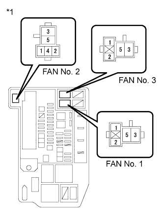 |
Remove the FAN No. 1 relay, FAN No. 2 relay and FAN No. 3 relay from the engine room relay block.
Turn the power switch on (IG).
Measure the voltage according to the value(s) in the table below.
| Tester Connection | Switch Condition | Specified Condition |
| 1 (FAN No. 1 relay) - Body ground | Power switch on (IG) | 11 to 14 V |
| 1 (FAN No. 2 relay) - Body ground | Power switch on (IG) | 11 to 14 V |
| 1 (FAN No. 3 relay) - Body ground | Power switch on (IG) | 11 to 14 V |
| *1 | Engine Room Relay Block |
Reinstall the FAN No. 1 relay, FAN No. 2 relay and FAN No. 3 relay.
|
| ||||
| OK | |
 |
| 3.INSPECT ENGINE ROOM RELAY BLOCK (FAN NO. 1 RELAY AND FAN NO. 3 RELAY VOLTAGE) |
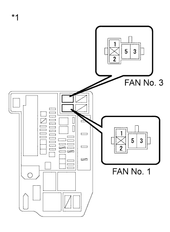 |
Remove the FAN No. 1 relay and FAN No. 3 relay from the engine room relay block.
Measure the voltage according to the value(s) in the table below.
| Tester Connection | Condition | Specified Condition |
| 3 (FAN No. 1 relay) - Body ground | Always | 11 to 14 V |
| 5 (FAN No. 3 relay) - Body ground | Always | 11 to 14 V |
| *1 | Engine Room Relay Block |
Reinstall the FAN No. 1 relay and FAN No. 3 relay.
|
| ||||
| OK | |
|
| 4.INSPECT FAN NO. 1 RELAY |
Inspect the FAN No. 1 relay (Click here).
|
| ||||
| OK | |
|
| 5.INSPECT FAN NO. 2 RELAY |
Inspect the FAN No. 2 relay (Click here).
|
| ||||
| OK | |
|
| 6.INSPECT FAN NO. 3 RELAY |
Inspect the FAN No. 3 relay (Click here).
|
| ||||
| OK | |
|
| 7.CHECK HARNESS AND CONNECTOR (FAN NO. 2 RELAY - BODY GROUND) |
Remove the FAN No. 2 relay from the engine room relay block.
Measure the resistance according to the value(s) in the table below.
| Tester Connection | Condition | Specified Condition |
| 5 (FAN No. 2 relay) - Body ground | Always | Below 1 Ω |
Reinstall the FAN No. 2 relay.
|
| ||||
| OK | |
|
| 8.INSPECT COOLING FAN MOTOR |
Inspect the cooling fan motor (Click here).
|
| ||||
| OK | |
|
| 9.CHECK HARNESS AND CONNECTOR (COOLING FAN MOTOR - BODY GROUND) |
Disconnect the cooling fan motor connector.
Measure the resistance according to the value(s) in the table below.
| Tester Connection | Condition | Specified Condition |
| A5-1 - Body ground | Always | Below 1 Ω |
Reconnect the cooling fan motor connector.
|
| ||||
| OK | |
|
| 10.CHECK HARNESS AND CONNECTOR (COOLING FAN MOTOR - ENGINE ROOM RELAY BLOCK) |
Disconnect the cooling fan motor connector.
Remove the FAN No. 1 relay and FAN No. 2 relay from the engine room relay block.
Measure the resistance according to the value(s) in the table below.
| Tester Connection | Condition | Specified Condition |
| A5-2 - 5 (FAN No. 1 relay) | Always | Below 1 Ω |
| A5-2 - 4 (FAN No. 2 relay) | Always | Below 1 Ω |
| Tester Connection | Condition | Specified Condition |
| A5-2 or 5 (FAN No. 1 relay) or 4 (FAN No. 2 relay) - Body ground | Always | 10 kΩ or higher |
Reconnect the cooling fan motor connector.
Reinstall the FAN No. 1 relay and FAN No. 2 relay.
|
| ||||
| OK | |
|
| 11.INSPECT NO. 2 COOLING FAN MOTOR |
Inspect the No. 2 cooling fan motor (Click here).
|
| ||||
| OK | |
|
| 12.CHECK HARNESS AND CONNECTOR (NO. 2 COOLING FAN MOTOR - ENGINE ROOM RELAY BLOCK) |
Disconnect the No. 2 cooling fan motor connector.
Remove the FAN No. 2 relay and FAN No. 3 relay from the engine room relay block.
Measure the resistance according to the value(s) in the table below.
| Tester Connection | Condition | Specified Condition |
| A6-1 - 3 (FAN No. 2 relay) | Always | Below 1 Ω |
| A6-2 - 3 (FAN No. 3 relay) | Always | Below 1 Ω |
| Tester Connection | Condition | Specified Condition |
| A6-1 or 3 (FAN No. 2 relay) - Body ground | Always | 10 kΩ or higher |
| A6-2 or 3 (FAN No. 3 relay) - Body ground | Always | 10 kΩ or higher |
Reconnect the No. 2 cooling fan motor connector.
Reinstall the FAN No. 2 relay and FAN No. 3 relay.
|
| ||||
| OK | |
|
| 13.INSPECT ENGINE ROOM RELAY BLOCK (FAN NO. 1 RELAY - FAN NO. 2 RELAY) |
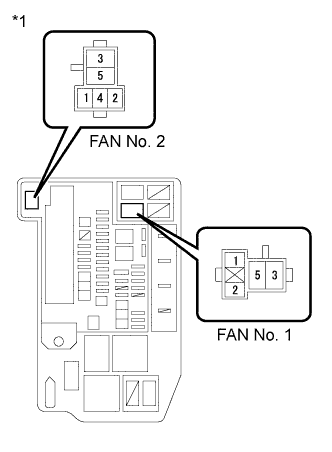 |
Remove the FAN No. 1 relay and FAN No. 2 relay from the engine room relay block.
Measure the resistance according to the value(s) in the table below.
| Tester Connection | Condition | Specified Condition |
| 2 (FAN No. 1 relay) - 2 (FAN No. 2 relay) | Always | Below 1 Ω |
| Tester Connection | Condition | Specified Condition |
| 2 (FAN No. 1 relay) or 2 (FAN No. 2 relay) - Body ground | Always | 10 kΩ or higher |
| *1 | Engine Room Relay Block |
Reinstall the FAN No. 1 relay and FAN No. 2 relay.
|
| ||||
| OK | |
|
| 14.CHECK HARNESS AND CONNECTOR (ENGINE ROOM RELAY BLOCK - ECM) |
Remove the FAN No. 2 relay and FAN No. 3 relay from the engine room relay block.
Disconnect the ECM connector.
Measure the resistance according to the value(s) in the table below.
| Tester Connection | Condition | Specified Condition |
| 2 (FAN No. 2 relay) - A60-22 (FANH) | Always | Below 1 Ω |
| 2 (FAN No. 3 relay) - A60-21 (FANL) | Always | Below 1 Ω |
| Tester Connection | Condition | Specified Condition |
| 2 (FAN No. 2 relay) or A60-22 (FANH) - Body ground | Always | 10 kΩ or higher |
| 2 (FAN No. 3 relay) or A60-21 (FANL) - Body ground | Always | 10 kΩ or higher |
Reconnect the ECM connector.
Reinstall the FAN No. 2 relay and FAN No. 3 relay.
|
| ||||
| OK | ||
| ||
| ||
| 15.CHECK HARNESS AND CONNECTOR (ENGINE ROOM RELAY BLOCK - NO. 2 INTEGRATION RELAY) |
Remove the FAN No. 1 relay, FAN No. 2 relay and FAN No. 3 relay from the engine room relay block.
Disconnect the No. 2 integration relay connector.
Measure the resistance according to the value(s) in the table below.
| Tester Connection | Condition | Specified Condition |
| 1 (FAN No. 1 relay) - 1B-4 | Always | Below 1 Ω |
| 1 (FAN No. 2 relay) - 1B-4 | Always | Below 1 Ω |
| 1 (FAN No. 3 relay) - 1B-4 | Always | Below 1 Ω |
| Tester Connection | Condition | Specified Condition |
| 1 (FAN No. 1 relay) or 1 (FAN No. 2 relay) or 1 (FAN No. 3 relay) or 1B-4 - Body ground | Always | 10 kΩ or higher |
Reinstall the FAN No. 1 relay, FAN No. 2 relay and FAN No. 3 relay.
Reconnect the No. 2 integration relay connector.
|
| ||||
| OK | ||
| ||
| ||
| 16.INSPECT FAN NO. 1 RELAY |
Inspect the FAN No. 1 relay (Click here).
|
| ||||
| OK | |
|
| 17.INSPECT FAN NO. 3 RELAY |
Inspect the FAN No. 3 relay (Click here).
|
| ||||
| OK | |
|
| 18.CHECK HARNESS AND CONNECTOR (ENGINE ROOM RELAY BLOCK - ECM) |
Remove the FAN No. 1 relay, FAN No. 2 relay and FAN No. 3 relay from the engine room relay block.
Disconnect the ECM connector.
Measure the resistance according to the value(s) in the table below.
| Tester Connection | Condition | Specified Condition |
| 2 (FAN No. 1 relay) or 2 (FAN No. 2 relay) or A60-22 (FANH) - Body ground | Always | 10 kΩ or higher |
| 2 (FAN No. 3 relay) or A60-21 (FANL) - Body ground | Always | 10 kΩ or higher |
Reinstall the FAN No. 1 relay, FAN No. 2 relay and FAN No. 3 relay.
Reconnect the ECM connector.
|
| ||||
| OK | |
|
| 19.CHECK HARNESS AND CONNECTOR (COOLING FAN MOTOR - ENGINE ROOM RELAY BLOCK) |
Remove the FAN No. 1 relay and the FAN No. 2 relay from the engine room relay block.
Disconnect the cooling fan motor connector.
Turn the power switch on (IG).
Measure the voltage according to the value(s) in the table below.
| Tester Connection | Switch Condition | Specified Condition |
| A5-2 - Body ground | Power switch on (IG) | 11 to 14 V |
Reinstall the FAN No. 1 and FAN No. 2 relay.
Reconnect the cooling fan motor connector.
|
| ||||
| OK | |
|
| 20.CHECK HARNESS AND CONNECTOR (NO. 2 COOLING FAN MOTOR - ENGINE ROOM RELAY BLOCK) |
Remove the FAN No. 3 relay from the engine room relay block.
Disconnect the No. 2 cooling fan motor connector.
Turn the power switch on (IG).
Measure the voltage according to the value(s) in the table below.
| Tester Connection | Switch Condition | Specified Condition |
| A6-2 - Body ground | Power switch on (IG) | 11 to 14 V |
Reinstall the FAN No. 3 relay.
Reconnect the No. 2 cooling fan motor connector.
|
| ||||
| OK | ||
| ||
| ||


