AIR FUEL RATIO SENSOR > INSTALLATION |
| 1. INSTALL AIR FUEL RATIO SENSOR |
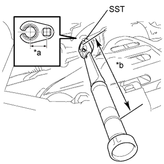 |
Using SST, install the air fuel ratio sensor.
| *a | Fulcrum Length 30 mm |
| *b | Fulcrum Length 300 mm |
Connect the air fuel ratio sensor connector and clamp.
| 2. INSTALL NO. 2 CYLINDER HEAD COVER |
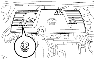 |
Engage the 3 clips to install the cover.
| 3. INSPECT FOR EXHAUST GAS LEAK |
| 4. INSTALL OUTER COWL TOP PANEL SUB-ASSEMBLY (for LHD) |
Install the outer cowl top panel sub-assembly with the 9 bolts.
w/ Wiper Deicer:
Engage the 3 clamps to install the wire harness.
Engage the clamp to install the wire harness.
| 5. INSTALL OUTER COWL TOP PANEL SUB-ASSEMBLY (for RHD) |
Install the outer cowl top panel sub-assembly with the 9 bolts.
w/ Wiper Deicer:
Engage the 3 clamps to install the wire harness.
Engage the clamp to install the wire harness.
| 6. INSTALL COWL BODY MOUNTING REINFORCEMENT LH (for LHD) |
Install the cowl body mounting reinforcement LH with the 2 bolts.
| 7. INSTALL COWL BODY MOUNTING REINFORCEMENT RH (for RHD) |
Install the cowl body mounting reinforcement RH with the 2 bolts.
| 8. INSTALL NO. 2 HEATER AIR DUCT SPLASH SHIELD SEAL (for LHD) |
Engage the claw and guide to install the No. 2 heater air duct splash shield seal.
| 9. INSTALL NO. 2 HEATER AIR DUCT SPLASH SHIELD SEAL (for RHD) |
Engage the claw and guide to install the No. 2 heater air duct splash shield seal.
| 10. INSTALL NO. 1 HEATER AIR DUCT SPLASH SHIELD SEAL (for LHD) |
Engage the 2 claws to install the No. 1 heater air duct splash shield seal.
| 11. INSTALL NO. 1 HEATER AIR DUCT SPLASH SHIELD SEAL (for RHD) |
Engage the 2 claws to install the No. 1 heater air duct splash shield seal.
| 12. INSTALL WINDSHIELD WIPER MOTOR AND LINK ASSEMBLY |
