DTC P0A7A-203 Generator Inverter Performance |
| DTC No. | INF Code | DTC Detection Condition | Trouble Area |
| P0A7A | 203 | Malfunction (short circuit) in the generator inverter inside the inverter with converter assembly |
|
| 1.CHECK HYBRID VEHICLE TRANSAXLE ASSEMBLY (MG1) |
Check that the service plug grip is not installed.
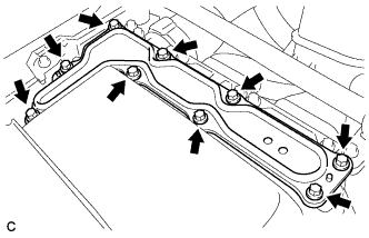 |
Remove the inverter cover from the inverter with converter assembly.
Disconnect the generator cable and motor cable from the inverter with converter assembly.
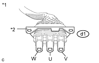 |
Check MG1 for an interphase short using a milliohmmeter.
Using a milliohmmeter, measure the resistance according to the value(s) in the table below.
| Tester Connection | Switch Condition | Specified Condition |
| d1-1 (W) - d1-2 (U) | Power switch off | 89.5 to 98.9 mΩ |
| d1-2 (U) - d1-3 (V) | Power switch off | 89.5 to 98.9 mΩ |
| d1-3 (V) - d1-1 (W) | Power switch off | 89.5 to 98.9 mΩ |
| *1 | Generator Cable |
| *2 | Shield Ground |
Using a megohmmeter set to 500 V, measure the resistance according to the value(s) in the table below.
| Tester Connection | Switch Condition | Specified Condition |
| d1-1 (W) - Body ground and shield ground | Power switch off | 100 MΩ or higher |
| d1-2 (U) - Body ground and shield ground | Power switch off | 100 MΩ or higher |
| d1-3 (V) - Body ground and shield ground | Power switch off | 100 MΩ or higher |
Connect the generator cable and motor cable.
Install the inverter cover.
|
| ||||
| OK | |
 |
| 2.REPLACE INVERTER WITH CONVERTER ASSEMBLY |
Replace the inverter with converter assembly (Click here).
|
| ||||
| 3.CHECK GENERATOR CABLE |
Check that the service plug grip is not installed.
Remove the generator cable.
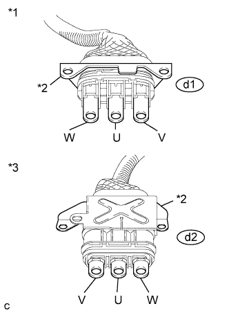 |
Using a megohmmeter set to 500 V, measure the resistance according to the value(s) in the table below.
| Tester Connection | Switch Condition | Specified Condition |
| d1-1 (W) - Body ground and shield ground | Power switch off | 100 MΩ or higher |
| d1-2 (U) - Body ground and shield ground | Power switch off | 100 MΩ or higher |
| d1-3 (V) - Body ground and shield ground | Power switch off | 100 MΩ or higher |
| *1 | Generator Cable (Inverter with Converter Assembly Side) |
| *2 | Shielded Ground |
| *3 | Generator Cable (Hybrid Vehicle Transaxle Assembly Side) |
Measure the resistance according to the value(s) in the table below.
| Tester Connection | Switch Condition | Specified Condition |
| d1-1 (W) - d2-3 (W) | Power switch off | Below 1 Ω |
| d1-2 (U) - d2-2 (U) | Power switch off | Below 1 Ω |
| d1-3 (V) - d2-1 (V) | Power switch off | Below 1 Ω |
| d1-1 (W) - d2-2 (U) | Power switch off | 100 MΩ or higher |
| d1-2 (U) - d2-1 (V) | Power switch off | 100 MΩ or higher |
| d1-3 (V) - d2-3 (W) | Power switch off | 100 MΩ or higher |
Install the generator cable.
|
| ||||
| OK | |
|
| 4.REPLACE HYBRID VEHICLE TRANSAXLE ASSEMBLY |
Replace the hybrid vehicle transaxle assembly (Click here).
| NEXT | |
|
| 5.REPLACE INVERTER WITH CONVERTER ASSEMBLY |
Replace the inverter with converter assembly (Click here).
|
| ||||
| 6.CHECK HYBRID VEHICLE TRANSAXLE ASSEMBLY |
Check that the service plug grip is not installed.
Remove the inverter with converter assembly.
Disconnect the generator cable from the hybrid vehicle transaxle assembly.
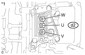 |
Check MG1 for an interphase short using a milliohmmeter.
Using a milliohmmeter, measure the resistance according to the value(s) in the table below.
| Tester Connection | Switch Condition | Specified Condition |
| d2-2 (U) - d2-1 (V) | Power switch off | 87.0 to 96.2 mΩ |
| d2-1 (V) - d2-3 (W) | Power switch off | 87.0 to 96.2 mΩ |
| d2-3 (W) - d2-2 (U) | Power switch off | 87.0 to 96.2 mΩ |
| *1 | Hybrid Vehicle Transaxle Assembly |
Using a megohmmeter set to 500 V, measure the resistance according to the value(s) in the table below.
| Tester Connection | Switch Condition | Specified Condition |
| d2-2 (U) - Body ground and shield ground | Power switch off | 100 MΩ or higher |
| d2-1 (V) - Body ground and shield ground | Power switch off | 100 MΩ or higher |
| d2-3 (W) - Body ground and shield ground | Power switch off | 100 MΩ or higher |
Connect the generator cable.
Install the inverter with converter assembly.
|
| ||||
| OK | |
|
| 7.REPLACE GENERATOR CABLE |
Replace the generator cable (Click here).
| NEXT | |
|
| 8.REPLACE INVERTER WITH CONVERTER ASSEMBLY |
Replace the inverter with converter assembly (Click here).
|
| ||||
| 9.REPLACE GENERATOR CABLE |
Replace the generator cable (Click here).
| NEXT | |
|
| 10.REPLACE HYBRID VEHICLE TRANSAXLE ASSEMBLY |
Replace the hybrid vehicle transaxle assembly (Click here).
| NEXT | |
|
| 11.REPLACE INVERTER WITH CONVERTER ASSEMBLY |
Replace the inverter with converter assembly (Click here).
| NEXT | |
|
| 12.CHECK DTC OUTPUT (HYBRID CONTROL) |
Check the other DTCs that were output together with DTC P0A7A-203.
| DTC No. | Relevant Diagnosis |
| P0A7A-122, 130, 322, 324, 325, 517, 518, 809, 810, 811 | Generator Inverter Performance |
| NEXT | ||
 | ||
| ||

