FUEL SENDER GAUGE ASSEMBLY > INSPECTION |
| 1. INSPECT FUEL SENDER GAUGE ASSEMBLY |
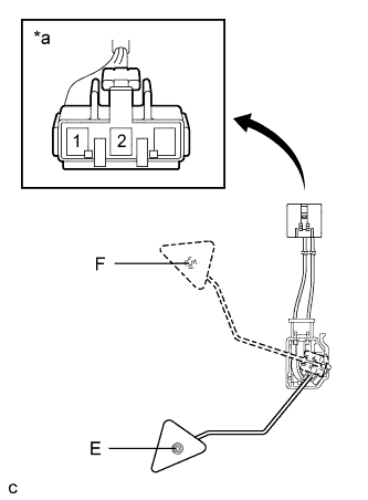 |
Check that the float moves smoothly between F and E.
| *a | Front view of wire harness connector (to Fuel Sender Gauge Assembly) |
Measure the resistance between terminals 1 and 2 of the connector according to the value(s) in the table below.
| Float Level | Resistance (Ω) |
| F | 12.0 to 18.0 |
| Between E and F | 12.0 to 415.0 (Gradually changes) |
| E | 405.0 to 415.0 |
