DTC U0122 Lost Communication with Vehicle Dynamics Control Module |
DTC U0123 Lost Communication with Yaw Rate Sensor Module |
DTC U0126 Lost Communication with Steering Angle Sensor Module |
DTC U0293 Lost Communication with HV ECU |
DTC U1104 Lost Communication with Driving Support ECU |
| DTC No. | DTC Detection Condition | Trouble Area |
| U0122 | While dynamic radar cruise control is either preparing for operation or operating and power switch is on (IG), communication stop between skid control ECU and driving support ECU assembly continues for 1 second or more |
|
| U0123 | While dynamic radar cruise control is either preparing for operation or operating and power switch is on (IG), communication stop between yaw rate sensor and driving support ECU assembly continues for 1 second or more |
|
| U0126 | While dynamic radar cruise control is either preparing for operation or operating and power switch is on (IG), communication stop between steering angle sensor and driving support ECU assembly continues for 1 second or more |
|
| U0293 | While dynamic radar cruise control is either preparing for operation or operating and power switch is on (IG), communication stop between power management control ECU and driving support ECU assembly or skid control ECU continues for 1 second or more |
|
| U1104 | While dynamic radar cruise control is either preparing for operation or operating and power switch is on (IG), communication stop between driving support ECU assembly and millimeter wave radar sensor assembly, power management control ECU, or brake booster with master cylinder (skid control ECU) continues for 1 second or more |
|
| 1.READ OUTPUT DTC |
Connect the intelligent tester to the DLC3.
Turn the power switch on (IG).
Turn the tester on.
Enter the following menus: Powertrain / Radar Cruise / DTC.
Enter the following menus: Powertrain / Hybrid Control / DTC.
Read the DTCs.
| Result | Proceed to |
| DTC U1104 is output (for Radar Cruise) | A |
| DTC U1104 is output (for Hybrid Control) | B |
| DTCs other than U1104 are output | B |
|
| ||||
| A | |
 |
| 2.CHECK CAN COMMUNICATION SYSTEM |
Using the intelligent tester to check if the CAN communication system is functioning normally (Click here).
| Result | Proceed to |
| CAN communication is normal | A |
| CAN communication is malfunctioning | B |
|
| ||||
| A | |
|
| 3.CHECK HARNESS AND CONNECTOR (DRIVING SUPPORT ECU - MILLIMETER WAVE RADAR SENSOR ASSEMBLY) |
Disconnect the driving support ECU assembly and millimeter wave radar sensor assembly connectors.
Measure the resistance according to the value(s) in the table below.
| Tester Connection | Condition | Specified Condition |
| H5-38 (LRRD) - A2-4 (LRRD) | Always | Below 1 Ω |
| Tester Connection | Condition | Specified Condition |
| H5-38 (LRRD) or A2-4 (LRRD) - Body ground | Always | 10 kΩ or higher |
Reconnect the driving support ECU assembly and millimeter wave radar sensor assembly connectors.
|
| ||||
| OK | |
|
| 4.CHECK HARNESS AND CONNECTOR (DRIVING SUPPORT ECU ASSEMBLY - BODY GROUND) |
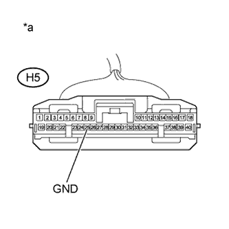 |
Disconnect the driving support ECU assembly connector.
Measure the resistance according to the value(s) in the table below.
| Tester Connection | Condition | Specified Condition |
| H5-25 (GND) - Body ground | Always | Below 1 Ω |
| *a | Front view of wire harness connector (to Driving Support ECU Assembly) |
Reconnect the driving support ECU assembly connector.
|
| ||||
| OK | |
|
| 5.REPLACE DRIVING SUPPORT ECU ASSEMBLY |
Replace the driving support control ECU assembly (Click here).
| NEXT | |
|
| 6.CHECK WHETHER DTC OUTPUT RECURS (DTC U1104) |
Connect the intelligent tester to DLC3.
Turn the power switch on (IG).
Clear the DTCs (Click here).
Perform the following to make sure that the DTC detection conditions are met.
Drive the vehicle at a speed of 50 km/h (30 mph) and 170 km/h (105 mph).
Turn the cruise control switch (ON-OFF button) on.
Push the -/SET switch to activate the cruise control.
Enter the following menus: Powertrain / Radar Cruise / DTC.
Read the DTCs.
| Result | Proceed to |
| DTC is not output | A |
| DTC U1104 is output | B |
|
| ||||
| A | ||
 | ||
| ||

