STEERING WHEEL > INSTALLATION |
| 1. INSTALL STEERING WHEEL HEATER CONTROL ASSEMBLY (w/ Steering Heater) |
Install the steering wheel heater control assembly to the lower steering wheel boss cover with the 2 screws.
Engage the clamp.
| 2. INSTALL LOWER STEERING WHEEL BOSS COVER (w/o Steering Heater) |
Engage the 4 claws to install the lower steering wheel boss cover to the steering wheel sub-assembly.
Install the 2 screws.
| 3. INSTALL LOWER STEERING WHEEL BOSS COVER (w/ Steering Heater) |
Connect the connector to the steering wheel heater control assembly.
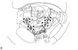 |
As shown in the illustration, place the wire harness along the guides.
Engage the 4 claws to install the lower steering wheel boss cover to the steering wheel sub-assembly.
Install the 2 screws.
| 4. INSTALL STEERING SHAKE DAMPER |
Install the steering shake damper to the steering wheel sub-assembly with the 2 screws.
| 5. INSTALL CRUISE CONTROL SWITCH WIRE (w/ Cruise Control System) |
Install the cruise control switch wire.
| 6. INSTALL CRUISE CONTROL SWITCH (w/ Cruise Control System) |
Connect the connector.
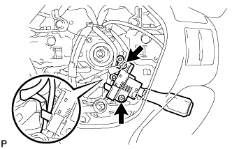 |
Install the cruise control switch with the 2 screws shown in the illustration.
| 7. INSTALL STEERING PAD SWITCH ASSEMBLY |
Engage the 2 claws, 2 pins and 2 guides to install the steering pad switch assembly.
Install the 2 screws.
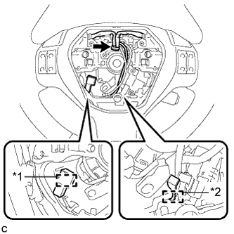 |
Install the clamp.
| *1 | Clamp |
| *2 | Guide |
Pass the wire harness through the guide.
Connect the steering pad switch connector to the spiral cable.
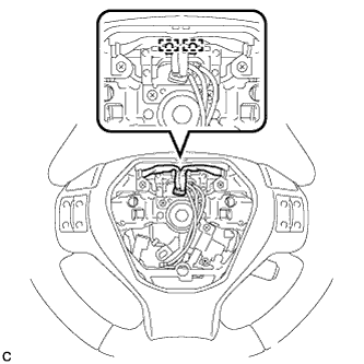 |
Pass the wire harness over the 2 guides.
| 8. ALIGN FRONT WHEELS FACING STRAIGHT AHEAD |
| 9. ADJUST SPIRAL CABLE WITH SENSOR SUB-ASSEMBLY |
Check that the power switch is off.
Check that the cable is disconnected from the negative (-) auxiliary battery terminal.
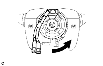 |
Rotate the spiral cable counterclockwise slowly by hand until it stops.
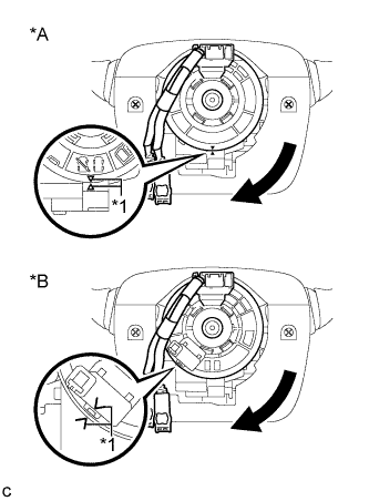 |
Rotate the spiral cable clockwise approximately 2.5 turns to align the marks.
| *A | w/o Steering Heater |
| *B | w/ Steering Heater |
| *1 | Alignment Mark |
| 10. INSTALL STEERING WHEEL ASSEMBLY |
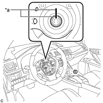 |
Install the steering wheel assembly aligning the matchmarks on the steering wheel assembly and steering main shaft.
| *a | Matchmark |
Install the steering wheel assembly set nut.
Connect the connectors to the spiral cable and steering wheel assembly.
| 11. CHECK STEERING WHEEL CENTER POINT |
| 12. INSTALL HORN BUTTON ASSEMBLY |
