DTC B2430 LED Headlight LH Circuit Malfunction |
DTC B2431 LED Headlight RH Circuit Malfunction |
| DTC No. | DTC Detection Condition | Trouble Area |
| B2430 | LED headlight LH circuit malfunction |
|
| B2431 | LED headlight RH circuit malfunction |
|
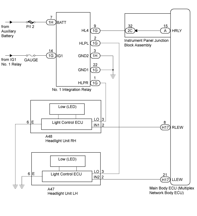
| 1.CHECK FOR DTC |
Clear the DTCs (Click here).
Check for DTCs (Click here).
| Result | Proceed to |
| Both DTC B2430 and B2431 are not output. | A |
| Both DTC B2430 and B2431 are output. | B |
| DTC B2430 or B2431 is output. | C |
|
| ||||
|
| ||||
| A | ||
 | ||
| ||
| 2.CHECK HARNESS AND CONNECTOR (NO. 1 INTEGRATION RELAY - AUXILIARY BATTERY AND BODY GROUND) |
Disconnect the 1G and 1H No. 1 integration relay connectors.
Measure the voltage and resistance according to the value(s) in the table below.
| Tester Connector | Condition | Specified Condition |
| 1G-14 (IG1) - Body ground | Power switch on (IG) | 11 to 14 V |
| 1H-7 (BATT) - Body ground | Power switch off | 11 to 14 V |
| Tester Connection | Condition | Specified Condition |
| 1G-22 (GND1) - Body ground | Always | Below 1 Ω |
| 1H-3 (GND2) - Body ground | Always | Below 1 Ω |
|
| ||||
| OK | |
 |
| 3.CHECK HARNESS AND CONNECTOR (NO. 1 INTEGRATION RELAY - INSTRUMENT PANEL JUNCTION BLOCK) |
Disconnect the 1G No. 1 integration relay connector.
Disconnect the 2C instrument panel junction block assembly connector.
Measure the resistance according to the value(s) in the table below.
| Tester Connection | Condition | Specified Condition |
| 1G-9 (HL4) - 2C-32 | Always | Below 1 Ω |
| 1G-9 (HL4) - Body ground | Always | 10 kΩ or higher |
|
| ||||
| OK | |
|
| 4.INSPECT INSTRUMENT PANEL JUNCTION BLOCK ASSEMBLY |
Remove the instrument panel junction block assembly.
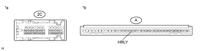
Measure the resistance according to the value(s) in the table below.
| Tester Connection | Condition | Specified Condition |
| 2C-32 - A-15 (HRLY) | Always | Below 1 Ω |
| 2C-32 - Body ground | Always | 10 kΩ or higher |
| *a | Component without harness connected (Instrument Panel Junction Block Assembly) | *b | Component without harness connected (Instrument Panel Junction Block Assembly) |
|
| ||||
| OK | |
|
| 5.REPLACE NO. 1 INTEGRATION RELAY |
Replace the No. 1 integration relay with a new or a known good one (Click here).
Check for DTCs (Click here).
|
| ||||
| OK | ||
| ||
| ||
| 6.INSPECT HEADLIGHT UNIT |
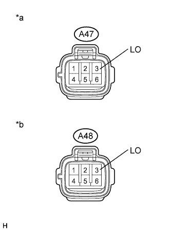 |
Disconnect the A47 or A48 headlight unit connector.
Measure the voltage according to the value(s) in the table below.
| Tester Connection | Switch Condition | Specified Condition |
| A47-3 (LO) - Body ground | Light control switch in head position | 11 to 14 V |
| Tester Connection | Switch Condition | Specified Condition |
| A48-3 (LO) - Body ground | Light control switch in head position | 11 to 14 V |
| *a | Front view of wire harness connector (to Headlight Unit LH) |
| *b | Front view of wire harness connector (to Headlight Unit RH) |
|
| ||||
| OK | |
|
| 7.INSPECT MAIN BODY ECU (MULTIPLEX NETWORK BODY ECU) |
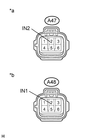 |
Disconnect the A47 or A48 headlight unit connector.
Measure the voltage according to the value(s) in the table below.
| Tester Connection | Switch Condition | Specified Condition |
| A47-2 (IN2) - Body ground | Light control switch in head position | 4.5 to 5.5 V |
| Tester Connection | Switch Condition | Specified Condition |
| A48-2 (IN1) - Body ground | Light control switch in head position | 4.5 to 5.5 V |
| *a | Front view of wire harness connector (to Headlight Unit LH) |
| *b | Front view of wire harness connector (to Headlight Unit RH) |
|
| ||||
| OK | |
|
| 8.CHECK HARNESS AND CONNECTOR (HEADLIGHT UNIT - BODY GROUND) |
Disconnect the A47 or A48 headlight unit connector.
Measure the resistance according to the value(s) in the table below.
| Tester Connection | Condition | Specified Condition |
| A47-6 (E) - Body ground | Always | Below 1 Ω |
| Tester Connection | Condition | Specified Condition |
| A48-6 (E) - Body ground | Always | Below 1 Ω |
|
| ||||
| OK | |
|
| 9.REPLACE LIGHT CONTROL ECU |
Replace the headlight control ECU with a new or a known good one (Click here).
Check for DTCs (Click here).
|
| ||||
| OK | ||
| ||
| ||
| 10.CHECK HARNESS AND CONNECTOR (HEADLIGHT UNIT - NO. 1 INTEGRATION RELAY) |
Disconnect the 1G No. 1 integration relay connector.
Disconnect the A47 or A48 headlight unit connector.
Measure the resistance according to the value(s) in the table below.
| Tester Connection | Condition | Specified Condition |
| 1G-2 (HLPL) - A47-3 (LO) | Always | Below 1 Ω |
| 1G-2 (HLPL) - Body ground | Always | 10 kΩ or higher |
| Tester Connection | Condition | Specified Condition |
| 1G-1 (HLPR) - A48-3 (LO) | Always | Below 1 Ω |
| 1G-1 (HLPR) - Body ground | Always | 10 kΩ or higher |
|
| ||||
| OK | ||
| ||
| ||
| 11.CHECK HARNESS AND CONNECTOR (MAIN BODY ECU - HEADLIGHT UNIT) |
Disconnect the H17 main body ECU (multiplex network body ECU) connector.
Disconnect the A47 or A48 headlight unit connector.
Measure the resistance according to the value(s) in the table below.
| Tester Connection | Condition | Specified Condition |
| H17-21 (LLEW) - A47-2 (IN2) | Always | Below 1 Ω |
| H17-21 (LLEW) - Body ground | Always | 10 kΩ or higher |
| Tester Connection | Condition | Specified Condition |
| H17-8 (RLEW) - A48-2 (IN1) | Always | Below 1 Ω |
| H17-8 (RLEW) - Body ground | Always | 10 kΩ or higher |
|
| ||||
| OK | ||
| ||
| ||


