PARKING ASSIST MONITOR SYSTEM > SYSTEM DESCRIPTION |
| GENERAL |
This system has a rear television camera assembly mounted on the back door to display the rear view of the vehicle on the multi-display. The display panel also shows a composite view consisting of the area behind the vehicle and parking guidelines to assist the driver in parking the vehicle by monitoring the area behind the vehicle.
This system consists of the following components:
Parking assist ECU
Rear television camera assembly
Multi-display
Display and navigation module display*1
Navigation computer sub-assembly*2
Power management control ECU
Skid control ECU
Spiral with sensor cable sub-assembly
This system is equipped with a self-diagnosis system, which is operated on a designated window that appears on the display panel, just as in the navigation system.
| FUNCTION OF COMPONENTS |
The parking assist ECU controls the system by using information from the following components.
| Item | Function |
| Rear Television Camera Assembly |
|
| Parking Assist ECU |
|
| Multi-display | Receives the video signals containing a composite of an image of the area behind the vehicle and parking assist guideline signals from the parking assist ECU, and displays them on the display panel. |
| Display and Navigation Module Display*1 Navigation Computer Sub-assembly*2 |
|
| Spiral with Sensor Cable Sub-assembly | Detects the angle of the steering wheel and sends the resulting signals to the parking assist ECU through CAN communication. |
| Power Management Control ECU | Sends the shift state signal to the display and navigation module display*1 or navigation computer sub-assembly*2 through CAN communication. |
| Skid control ECU | Transmits a vehicle speed signal to the parking assist ECU. |
| OPERATION EXPLANATION |
The reverse signal is sent to the display and navigation module display*1 or navigation computer sub-assembly*2 when the shift lever is moved to R.
After receiving the reverse position signal, the display and navigation module display*1 or navigation computer sub-assembly*2 switches the display signal for the multi-display from the navigation system to the parking assist monitor system.
In parallel parking assist mode, an appropriate steering angle and timing information can be provided for the driver. This is based on the information from the steering angle sensor signal and the vehicle angle data signal that are sent to the parking assist ECU.
| DISPLAY MODE SETTING |
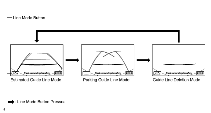
While the parking assist monitor is displayed, pressing the line mode button switches the parking assist monitor display mode.
| Parking Assist Monitor Display Mode | Distance Guide Line (Red with Black) | Vehicle Width Extension Line (Green) | Predicted Path Line (Yellow) | Parking Guide Line (Green) |
| Estimated Guide Line Mode | Displayed | Displayed | Displayed | Not displayed |
| Parking Guide Line Mode | Displayed | Displayed | Not displayed | Displayed |
| Guide Line Deletion Mode | Displayed | Not displayed | Not displayed | Not displayed |
| COMMUNICATION SYSTEM OUTLINE |
The components of the parking assist monitor system communicate with each other through the AVC-LAN. Also, parallel parking assist mode judges the vehicle angle data transmitted via the AVC-LAN from the display and navigation module display*1 or navigation computer sub-assembly*2 (the data is calculated by the display and navigation module display*1 or navigation computer sub-assembly*2 by integrating the yaw rate of the gyro sensor built into the display and navigation module display*1 or navigation computer sub-assembly*2).
If a short circuit or open circuit occurs in the AVC-LAN, communication is interrupted and the parking assist monitor system will stop functioning.
| DIAGNOSTIC FUNCTION OUTLINE |
This parking assist monitor system has a diagnostic function displayed in the multi-display. This function enables calibration (adjustment and verify) of the parking assist monitor system (Click here).
The following items for the parking assist monitor system can be checked using the intelligent tester.
| Item | Proceed to |
| DTC |
Click here
|
| Data List / Active Test |
Click here
|
