PARKING ASSIST MONITOR SYSTEM > CALIBRATION |
| ADJUST PARKING ASSIST MONITOR SYSTEM |
This parking assist monitor system can be adjusted using from the diagnostic screen of the multi-display.
If the following operations are performed, it is necessary to perform adjustments and checks using the diagnostic screen.
| Part Name | Operation | Adjustment Item | Proceed to |
| Spiral with sensor cable sub-assembly |
| Steering angle neutral point (Initialize parking assist monitor system) |
Click here
|
| Steering angle setting |
Click here
| ||
| Spiral with sensor cable sub-assembly | Replacement | Steering angle neutral point (Initialize parking assist monitor system) |
Click here
|
| Steering angle setting |
Click here
| ||
| Parking assist ECU | Replacement | Parking assist ECU initialization | Procedure 2 |
| Suspension, tires, etc. | The vehicle height changes because of suspension or tire replacement | Rear television camera optical axis (Back camera position setting) | Procedure 3 |
| Rear television camera assembly |
| Rear television camera optical axis (Back camera position setting) | Procedure 3 |
| Specification | Waiting Time |
| Navigation System (for HDD) | 60 sec. |
| PARKING ASSIST ECU INITIALIZATION (PROCEDURE 2) |
Preparation for adjustment
Park the vehicle with the steering wheel centered.
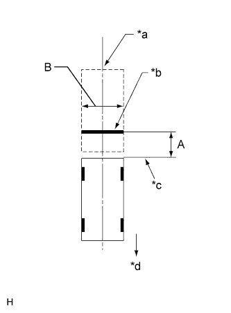 |
Set a target bar for optical axis adjustment of the rear television camera assembly.
| Area | Specification |
| A | 1355 to 1365 mm (4.446 to 4.478 ft.) |
| B | 1995 to 2005 mm (6.545 to 6.578 ft.) |
| *a | Vehicle Center |
| *b | Target Bar for Back Camera Adjustment |
| *c | Vehicle End |
| *d | Front Side |
Start diagnostic mode (Click herefor DVD) (Click here for HDD).
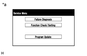 |
Select "Function Check/Setting" on the Service Menu screen.
| *a | Example |
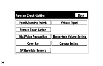 |
Select "Camera Setting" on the Function Check/Setting screen.
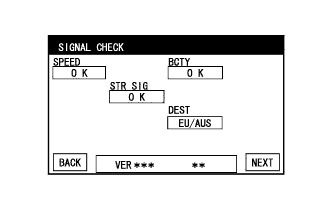 |
Select "NEXT" on the SIGNAL CHECK screen.
STEERING ANGLE SETTING
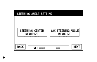 |
Perform the STEERING CENTER MEMORIZE operation.
Perform the MAX STEERING ANGLE MEMORIZE operation.
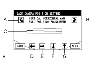 |
BACK CAMERA POSITION SETTING
Perform roll angle adjustment.
Perform vertical and horizontal position adjustment.
Select the "NEXT" button on the BACK CAMERA POSITION SETTING screen.
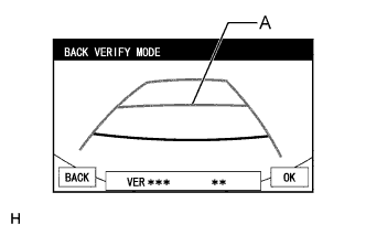 |
BACK VERIFY MODE
Check that A and the target adjustment bar are overlapping.
Selecting "OK" will return to the Service Menu screen, and complete the adjustment.
Finish diagnostic mode (Click herefor DVD) (Click here for HDD).
| BACK CAMERA POSITION SETTING (PROCEDURE 3) |
Preparation for adjustment
Park the vehicle with the steering wheel centered.
|
Set a target bar behind the vehicle for optical axis adjustment of the rear television camera (back camera position setting).
| Area | Specification |
| A | 1355 to 1365 mm (4.446 to 4.478 ft.) |
| B | 1995 to 2005 mm (6.545 to 6.578 ft.) |
| *a | Vehicle Center |
| *b | Target Bar for Back Camera Position Setting |
| *c | Vehicle End |
| *d | Front Side |
Start diagnostic mode (Click herefor DVD) (Click here for HDD).
|
Select "Function Check/Setting" on the Service Menu screen.
| *a | Example |
|
Select "Camera Setting" on the Function Check/Setting screen.
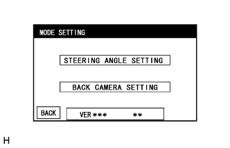 |
Select "BACK CAMERA SETTING" on the MODE SETTING screen.
|
Select "NEXT" on the SIGNAL CHECK screen.
|
BACK CAMERA POSITION SETTING
Perform roll angle adjustment.
Perform vertical and horizontal position adjustment.
Select the "NEXT" button on the "BACK CAMERA POSITION SETTING" screen.
|
BACK VERIFY MODE
Check that A and the target adjustment bar are overlapping.
Selecting "OK" will return to the Service Menu, and complete the adjustment.
Finish diagnostic mode (Click herefor DVD) (Click here for HDD).
