DTC C1621 Back Camera Power Supply Failure |
DTC C1622 Open or Short Circuit in Back Camera Signal |
| DTC No. | DTC Detection Condition | Trouble Area |
| C1621 | Rear television camera power supply failure |
|
| C1622 | Open or short in the rear television camera signal circuit |
|
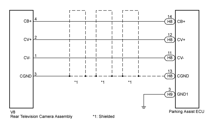
| 1.CHECK HARNESS AND CONNECTOR (PARKING ASSIST ECU - REAR TELEVISION CAMERA) |
Disconnect the H8 connector from the parking assist ECU.
Disconnect the V8 connector from the rear television camera assembly.
Measure the resistance according to the value(s) in the table below.
| Tester Connection | Condition | Specified Condition |
| H8-11 (CV-) - V8-1 (CV-) | Always | Below 1 Ω |
| H8-12 (CV+) - V8-2 (CV+) | Always | Below 1 Ω |
| H8-13 (CGND) - V8-3 (CGND) | Always | Below 1 Ω |
| H8-14 (CB+) - V8-4 (CB+) | Always | Below 1 Ω |
| H8-11 (CV-) - Body ground | Always | 10 kΩ or higher |
| H8-12 (CV+) - Body ground | Always | 10 kΩ or higher |
| H8-13 (CGND) - Body ground | Always | 10 kΩ or higher |
| H8-14 (CB+) - Body ground | Always | 10 kΩ or higher |
|
| ||||
| OK | |
 |
| 2.CHECK PARKING ASSIST ECU (CV-, CGND) |
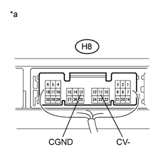 |
Reconnect the H8 connector to the parking assist ECU.
Measure the resistance according to the value(s) in the table below.
| Tester Connection | Condition | Specified Condition |
| H8-11 (CV-) - Body ground | Always | Below 1 Ω |
| H8-13 (CGND) - Body ground | Always | Below 1 Ω |
| *a | Component with harness connected (Parking Assist ECU) |
|
| ||||
| OK | |
|
| 3.CHECK REAR TELEVISION CAMERA ASSEMBLY (CB+, CGND) |
Disconnect the V8 connector from the rear television camera assembly.
Measure the voltage according to the value(s) in the table below.
| Tester Connection | Condition | Specified Condition |
| V8-4 (CB+) - V8-3 (CGND) | Power switch on (READY) Reverse (R) selected | 5.5 to 7.0 V |
|
| ||||
| OK | |
|
| 4.CHECK PARKING ASSIST ECU (CV+, GND1) |
Reconnect the V8 connector to the rear television camera assembly.
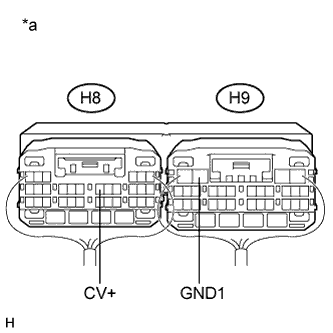 |
Reconnect the H9 connector to the parking assist ECU.
| *a | Component with harness connected (Parking Assist ECU) |
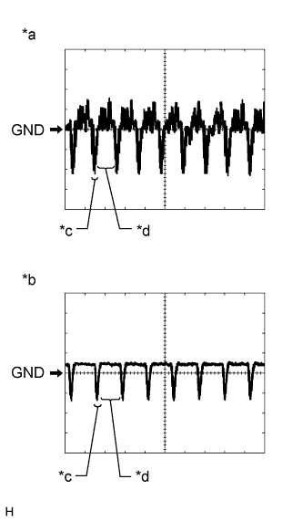 |
Check the waveform of the rear television camera assembly using an oscilloscope.
| Item | Content |
| Terminal No. (Symbol) | H8-12 (CV+) - H9-3 (GND1) |
| Tool Setting | 200 mV/DIV., 50 μsec./DIV. |
| Condition | Power switch on (READY), reverse (R) selected |
| *a | Waveform 1 (camera lens is not covered, displaying an image) |
| *b | Waveform 2 (camera lens is covered, blacking out the screen) |
| *c | Synchronization Signal |
| *d | Video Waveform |
|
| ||||
| OK | ||
 | ||
| ||

