HYBRID CONTROL SYSTEM > Pattern Select Switch Eco Mode Circuit |
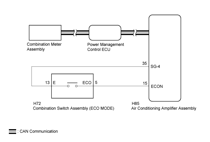
| 1.READ VALUE USING INTELLIGENT TESTER (CAN BUS CHECK) |
Connect the intelligent tester to the DLC3.
Turn the power switch on (IG).
Enter the following menus: System Select / CAN Bus Check.
| Result | Proceed to |
| All of the ECUs and sensors that are currently connected to the CAN communication system are displayed. | A |
| None of the ECUs and sensors that are currently connected to the CAN communication system are displayed, or some of them are not displayed. | B |
Turn the power switch off.
|
| ||||
| A | |
 |
| 2.CHECK DTC OUTPUT (ALL CODES) |
Connect the intelligent tester to the DLC3.
Turn the power switch on (IG).
Enter the following menus: System Select / Utility / All Codes.
Check DTCs.
| Result | Proceed to |
| No DTCs are output. | A |
| DTCs are output. | B |
Turn the power switch off.
|
| ||||
| A | |
|
| 3.PERFORM ACTIVE TEST USING INTELLIGENT TESTER (INDICAT. ECO MODE) |
Connect the intelligent tester to the DLC3.
Turn the power switch on (IG).
Enter the following menus: Body / Combination Meter / Active Test / Indicat. ECO Mode.
Perform the "Indicat. ECO MODE" Active Test.
Turn the power switch off.
|
| ||||
| OK | |
|
| 4.READ VALUE USING INTELLIGENT TESTER (ECO MODE) |
Connect the intelligent tester to the DLC3.
Turn the power switch on (IG).
Enter the following menus: Powertrain / Hybrid Control / Data List / ECO Mode.
Read the value displayed on the intelligent tester.
| Tester Display | Measurement Item/Range | Normal Condition |
| ECO Mode | ECO mode transition availability/ ON or OFF | In ECO mode: ON |
| Result | Proceed to |
| The intelligent tester display changes according to the mode switch (ECO mode) operation. | A |
| The intelligent tester display does not changes according to the mode switch (ECO mode) operation. | B |
|
| ||||
| A | ||
 | ||
| ||
| 5.READ VALUE USING INTELLIGENT TESTER (ECO SWITCH) |
Connect the intelligent tester to the DLC3.
Turn the power switch on (IG).
Enter the following menus: Body / Air Conditioning / Data List / ECO Switch.
Read the value displayed on the intelligent tester.
| Tester Display | Measurement Item/Range | Normal Condition |
| ECO Switch | Mode switch (ECO mode) condition/ ON or OFF | Mode switch being turned and held at ECO position: ON Mode switch not turned: OFF |
| Result | Proceed to |
| The intelligent tester display changes according to the mode switch (ECO mode) operation. | A |
| The intelligent tester display does not changes according to the mode switch (ECO mode) operation. | B |
|
| ||||
| A | ||
| ||
| ||
| 6.CHECK COMBINATION SWITCH ASSEMBLY (ECO MODE / NORMAL MODE) |
Remove the combination switch assembly.
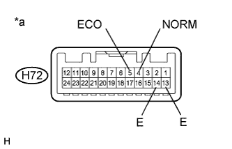 |
Measure the resistance according to the value(s) in the table below.
| Tester Connection | Condition | Specified Condition |
| H72-5 (ECO) - H72-13 (E) | Mode switch being turned and held at ECO position | Below 1 Ω |
| Mode switch not turned | 10 kΩ or higher | |
| H72-4 (NORM) - H72-14 (E) | Mode switch being pushed and held | Below 1 Ω |
| Mode switch not pushed | 10 kΩ or higher |
| *a | Component without harness connected (Combination Switch Assembly) |
Install the combination switch assembly.
|
| ||||
| OK | |
|
| 7.CHECK HARNESS AND CONNECTOR (AIR CONDITIONING AMPLIFIER ASSEMBLY - COMBINATION SWITCH) |
Disconnect connector H85 from the air conditioning amplifier assembly.
Disconnect connector H72 from the combination switch assembly.
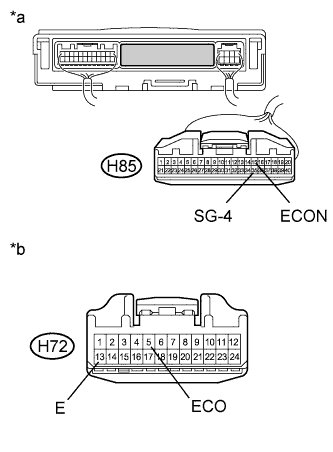 |
Measure the resistance according to the value(s) in the table below.
| Tester Connection | Condition | Specified Condition |
| H85-15 (ECON) - H72-5 (ECO) | Always | Below 1 Ω |
| H85-15 (ECON) or H72-5 (ECO) - Body ground | Always | 10 kΩ or higher |
| H85-35 (SG-4) - H72-13 (E) | Always | Below 1 Ω |
| *a | Front view of wire harness connector (to Air Conditioning Amplifier Assembly) |
| *b | Front view of wire harness connector (to Combination Switch Assembly) |
Connect the combination switch assembly connector.
Connect the air conditioning amplifier assembly connector.
|
| ||||
| OK | |
|
| 8.CHECK HARNESS AND CONNECTOR (COMBINATION SWITCH ASSEMBLY - BODY GROUND) |
Disconnect connector H72 from the combination switch assembly.
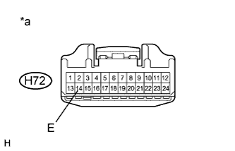 |
Measure the resistance according to the value(s) in the table below.
| Tester Connection | Condition | Specified Condition |
| H72-14 (E) - Body ground | Always | Below 1 Ω |
| *a | Front view of wire harness connector (to Combination Switch Assembly) |
Connect the combination switch assembly connector.
|
| ||||
| OK | |
|
| 9.CHECK HARNESS AND CONNECTOR (ECM - COMBINATION SWITCH ASSEMBLY) |
Disconnect connector A60 from the ECM.
Disconnect connector H72 from the combination switch assembly.
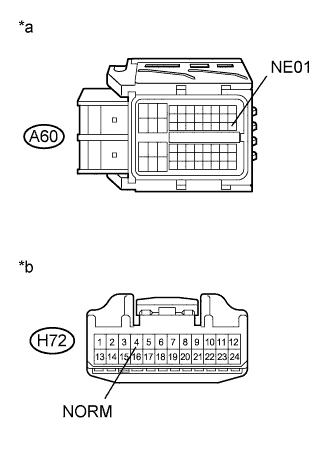 |
Measure the resistance according to the value(s) in the table below.
| Tester Connection | Condition | Specified Condition |
| A60-30 (NE01) - H72-4 (NORM) | Always | Below 1 Ω |
| A60-30 (NE01) or H72-4 (NORM) - Body ground | Always | 10 kΩ or higher |
| *a | Front view of wire harness connector (to ECM) |
| *b | Front view of wire harness connector (to Combination Switch Assembly) |
Connect the combination switch assembly connector.
Connect the ECM connector.
|
| ||||
| OK | ||
| ||
| ||


