GLOVE BOX LIGHT > INSTALLATION |
| 1. INSTALL GLOVE BOX LIGHT ASSEMBLY |
Engage the 2 claws to install the glove box light assembly.
| 2. INSTALL GLOVE COMPARTMENT DOOR ASSEMBLY |
Connect the connector.
Engage the clamp.
Engage the 5 claws.
Install the glove compartment door assembly with the 4 screws <C>.
| 3. INSTALL LOWER NO. 2 INSTRUMENT PANEL AIRBAG ASSEMBLY |
Check that the power switch is off.
Check that the cable is disconnected from the negative (-) auxiliary battery terminal.
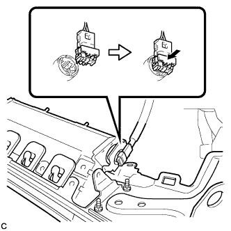 |
Connect the airbag connector to the lower No. 2 instrument panel airbag assembly.
Push in the lock to install the airbag connector.
Temporarily install the lower No. 2 instrument panel airbag assembly with the 6 claws and 2 guides.
Install the 3 bolts.
| 4. INSTALL NO. 2 INSTRUMENT PANEL UNDER COVER SUB-ASSEMBLY |
| 5. INSTALL INSTRUMENT SIDE PANEL RH |
Connect the connector.
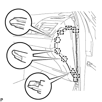 |
Engage the 4 guides, clip and 3 claws to install the instrument side panel RH.
| 6. INSTALL FRONT DOOR OPENING TRIM WEATHERSTRIP RH |
| 7. INSTALL COWL SIDE TRIM SUB-ASSEMBLY RH |
| 8. INSTALL FRONT DOOR SCUFF PLATE RH |
| 9. CONNECT CABLE TO NEGATIVE BATTERY TERMINAL |
| 10. INSTALL REAR FLOOR BOARD UPPER NO. 3 PLATE |
Engage the 4 claws and 2 guides to install the rear floor board upper No. 3 plate.
| 11. INSTALL DECK FLOOR BOX RH |
Engage the 6 guides.
Install the deck floor box RH with the clip.
| 12. INSTALL REAR NO. 3 FLOOR BOARD |
Install the rear No. 3 floor board.
| 13. INSTALL REAR DECK FLOOR BOX |
Install the rear deck floor box.
| 14. INSTALL REAR NO. 2 FLOOR BOARD |
Install the rear No. 2 floor board.
| 15. PERFORM DIAGNOSTIC SYSTEM CHECK |
| 16. INSPECT SRS WARNING LIGHT |
