STOP LIGHT SWITCH > INSTALLATION |
| 1. INSTALL STOP LIGHT SWITCH ASSEMBLY |
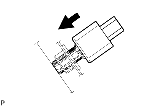 |
Insert the stop light switch assembly until the rod hits the pedal.
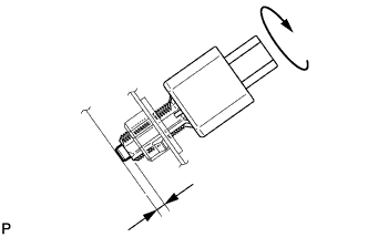 |
Make a quarter turn clockwise to install the stop light switch assembly.
Connect the connector.
Check the protrusion of the rod.
| 2. INSTALL NO. 1 INSTRUMENT PANEL UNDER COVER SUB-ASSEMBLY (for LHD) |
Connect each connector.
Engage the clamp.
Engage the clip.
Install the No. 1 instrument panel under cover sub-assembly with the 2 screws <E>.
| 3. INSTALL NO. 1 INSTRUMENT PANEL UNDER COVER SUB-ASSEMBLY (for RHD) |
Connect each connector.
Engage the clamp.
Engage the 2 clips.
Install the No. 1 instrument panel under cover sub-assembly with the screw <E>.
