DTC C1AEC Front Sensor Communication Malfunction |
| DTC No. | DTC Detection Condition | Trouble Area |
| C1AEC | An open or short circuit in the communication line between the front sensors and ECU or a malfunction in a front sensor during initialization mode after the power switch is turned on (IG). |
|
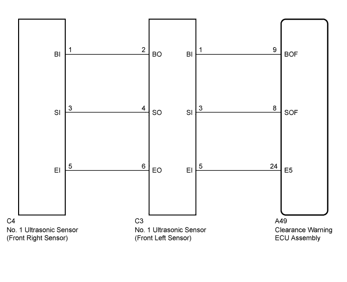
| 1.CHECK DTC OUTPUT (C1AEC) |
Check for DTCs (Click here).
Clear the DTCs (Click here).
Recheck for DTCs (Click here).
| Result | Proceed to |
| DTC C1AEC is output | A |
| No DTC is output | B |
|
| ||||
| A | |
 |
| 2.CHECK HARNESS AND CONNECTOR (CLEARANCE WARNING ECU - FRONT LEFT SENSOR) |
Disconnect the A49 connector from the clearance warning ECU.
Disconnect the C3 connector from the No. 1 ultrasonic sensor.
Measure the resistance according to the value(s) in the table below.
| Tester Connection | Condition | Specified Condition |
| A49-9 (BOF) - C3-1 (BI) | Always | Below 1 Ω |
| A49-8 (SOF) - C3-3 (SI) | ||
| A49-24 (E5) - C3-5 (EI) | ||
| A49-9 (BOF) - Body ground | 10 kΩ or higher | |
| A49-8 (SOF) - Body ground | ||
| A49-24 (E5) - Body ground |
|
| ||||
| OK | |
|
| 3.CHECK HARNESS AND CONNECTOR (FRONT LEFT SENSOR - FRONT RIGHT SENSOR) |
Disconnect the C3 and C4 connectors from the No. 1 ultrasonic sensors.
Measure the resistance according to the value(s) in the table below.
| Tester Connection | Condition | Specified Condition |
| C3-2 (BO) - C4-1 (BI) | Always | Below 1 Ω |
| C3-4 (SO) - C4-3 (SI) | ||
| C3-6 (EO) - C4-5 (EI) | ||
| C3-2 (BO) - Body ground | 10 kΩ or higher | |
| C3-4 (SO) - Body ground | ||
| C3-6 (EO) - Body ground |
|
| ||||
| OK | |
|
| 4.CHECK NO. 1 ULTRASONIC SENSOR (FRONT LEFT SENSOR) |
Remove the No. 1 ultrasonic sensor (front left sensor) (Click here).
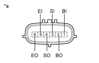 |
Measure the resistance according to the value(s) in the table below.
| Tester Connection | Condition | Specified Condition |
| 1 (BI) - 5 (EI) | Always | 10 kΩ or higher |
| 1 (BI) - 2 (BO) | ||
| 3 (SI) - 4 (SO) | Below 1 Ω | |
| 5 (EI) - 6 (EO) |
| *a | Component without harness connected (No. 1 Ultrasonic Sensor (Front Left Sensor)) |
|
| ||||
| OK | |
|
| 5.REPLACE NO. 1 ULTRASONIC SENSOR (FRONT LEFT SENSOR) |
Replace the No. 1 ultrasonic sensor (front left sensor) with a known good one (Click here).
| NEXT | |
|
| 6.CHECK DTC OUTPUT (C1AEC) |
Clear the DTCs (Click here).
Check for DTCs (Click here).
| Result | Proceed to |
| DTC C1AEC is output | A |
| No DTC is output | B |
|
| ||||
| A | |
|
| 7.REPLACE NO. 1 ULTRASONIC SENSOR (FRONT RIGHT SENSOR) |
Replace the No. 1 ultrasonic sensor (front right sensor) with a known good one (Click here).
| NEXT | |
|
| 8.CHECK DTC OUTPUT (C1AEC) |
Clear the DTCs (Click here).
Check for DTCs (Click here).
| Result | Proceed to |
| DTC C1AEC is output | A |
| No DTC is output | B |
|
| ||||
| A | ||
 | ||
| ||

