DTC B2650 Slide Sensor Malfunction |
| DTC Code | DTC Detection Condition | Trouble Area |
| B2650 | The forward and backward lock detection position of the sensor is the same. |
|
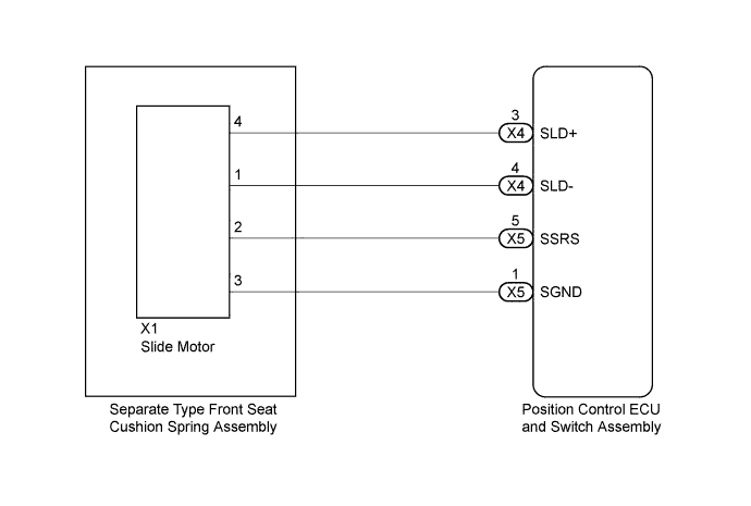
| for LHD |
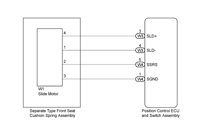
| for RHD |
| 1.PERFORM ACTIVE TEST USING INTELLIGENT TESTER (SLIDE MOTOR) |
Turn the power switch off.
Connect the intelligent tester to the DLC3.
Turn the power switch on (IG).
Turn the intelligent tester on.
Enter the following menus: Body / Driver Seat / Active Test.
Perform the Active Test according to the display on the intelligent tester.
| Tester Display | Test Part | Control Range | Diagnostic Note |
| Seat Slide Operation | Seat sliding operation | Front / OFF / Rear | - |
|
| ||||
| OK | |
 |
| 2.CHECK POSITION CONTROL ECU AND SWITCH ASSEMBLY (SLIDE MOTOR CIRCUIT) |
Disconnect the X1*1 or W1*2 slide motor connector.
Measure the voltage according to the value(s) in the table below.
| Tester Connection | Switch Condition | Specified Condition |
| X1-2 - X1-3 | Sliding switch on | 4.8 to 5.1 V |
| Tester Connection | Switch Condition | Specified Condition |
| W1-2 - W1-3 | Sliding switch on | 4.8 to 5.1 V |
|
| ||||
| OK | |
|
| 3.CHECK SLIDE MOTOR (SEPARATE TYPE FRONT SEAT CUSHION SPRING ASSEMBLY) |
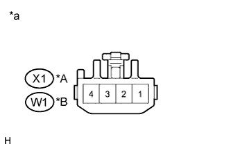 |
Reconnect the X1*1 or W1*2 slide motor connector.
Measure the voltage according to the value(s) in the table below.
| Tester Connection | Switch Condition | Specified Condition |
| X1-2 - Body ground | Sliding switch on | 4.5 to 4.8 V |
| Tester Connection | Switch Condition | Specified Condition |
| W1-2 - Body ground | Sliding switch on | 4.5 to 4.8 V |
| *A | for LHD |
| *B | for RHD |
| *a | Component with harness connected (Slide Motor (Separate Type Front Seat Cushion Spring Assembly)) |
|
| ||||
| OK | ||
 | ||
| ||
| 4.CHECK HARNESS AND CONNECTOR (POSITION CONTROL ECU AND SWITCH ASSEMBLY - SLIDE MOTOR) |
Disconnect the X5*1 or W4*2 switch connector.
Measure the resistance according to the value(s) in the table below.
| Tester Connection | Condition | Specified Condition |
| X5-5 (SSRS) - X1-2 | Always | Below 1 Ω |
| X5-1 (SGND) - X1-3 | Always | Below 1 Ω |
| X5-5 (SSRS) - Body ground | Always | 10 kΩ or higher |
| X5-1 (SGND) - Body ground | Always | 10 kΩ or higher |
| Tester Connection | Condition | Specified Condition |
| W4-5 (SSRS) - W1-2 | Always | Below 1 Ω |
| W4-1 (SGND) - W1-3 | Always | Below 1 Ω |
| W4-5 (SSRS) - Body ground | Always | 10 kΩ or higher |
| W4-1 (SGND) - Body ground | Always | 10 kΩ or higher |
|
| ||||
| OK | ||
| ||
| ||
| 5.INSPECT SLIDE MOTOR (SEPARATE TYPE FRONT SEAT CUSHION SPRING ASSEMBLY) |
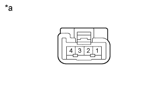 |
Disconnect the X1*1 or W1*2 slide motor connector.
Check if the seat cushion spring moves smoothly when the auxiliary battery is connected to the slide motor connector terminals.
| Measurement Condition | Operational Direction |
| Auxiliary battery positive (+) → 4 Auxiliary battery negative (-) → 1 | Seat cushion spring moves forward |
| Auxiliary battery positive (+) → 1 Auxiliary battery negative (-) → 4 | Seat cushion spring moves backward |
| *a | Component without harness connected (Slide Motor (Separate Type Front Seat Cushion Spring Assembly)) |
|
| ||||
| OK | |
|
| 6.CHECK HARNESS AND CONNECTOR (POSITION CONTROL ECU AND SWITCH ASSEMBLY - SLIDE MOTOR) |
Disconnect the X4*1 or W3*2 position control ECU and switch assembly connector.
Measure the resistance according to the value(s) in the table below.
| Tester Connection | Condition | Specified Condition |
| X4-3 (SLD+) - X1-4 | Always | Below 1 Ω |
| X4-4 (SLD-) - X1-1 | Always | Below 1 Ω |
| X4-3 (SLD+) - Body ground | Always | 10 kΩ or higher |
| X4-4 (SLD-) - Body ground | Always | 10 kΩ or higher |
| Tester Connection | Condition | Specified Condition |
| W3-3 (SLD+) - W1-4 | Always | Below 1 Ω |
| W3-4 (SLD-) - W1-1 | Always | Below 1 Ω |
| W3-3 (SLD+) - Body ground | Always | 10 kΩ or higher |
| W3-4 (SLD-) - Body ground | Always | 10 kΩ or higher |
|
| ||||
| OK | ||
| ||
| ||


