NAVIGATION SYSTEM (for DVD) > OPERATION CHECK

for Preparation Click here


CHECK SYSTEM NORMAL CONDITION
  1. If the symptom is applicable to any of the following, it is intended behavior, and not a malfunction.

    Symptom
    Answer
    A longer route than expected is chosen.
    Depending on the road conditions, the display and navigation module display may determine that a longer route is quicker.
    Even when distance priority is high, the shortest route is not shown.
    Some routes may not be advised due to safety concerns.
    When the vehicle is put into motion immediately after the hybrid system starts, the navigation system deviates from the correct position.
    If the vehicle starts before the navigation system activates, the system may not react.
    When driving on certain types of roads, especially new roads, the vehicle position deviates from the correct position.
    When the vehicle is driving on new roads not available on the map data from the map disc, the system attempts to match it to another nearby road, causing the position mark to deviate.


  2. I100066
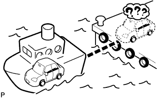
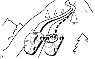
  3. The following symptoms are not malfunctions, but are caused by errors inherent in the GPS, gyro sensor, speed sensor or display and navigation module display.

    1. The current position mark may be displayed on a nearby parallel road.
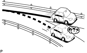


    2. I100067
    3. Immediately after a fork in the road, the current vehicle position mark may be displayed on the wrong road.
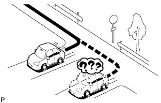


    4. I100068
    5. When the vehicle turns right or left at an intersection, the current vehicle position mark may be displayed on a nearby parallel road.


    6. I100069
    7. When the vehicle is carried, such as on a ferry, and the vehicle itself is not driving, the current vehicle position mark may be displayed in the position where the vehicle was until a measurement can be performed by the GPS.


    8. I100070
    9. When the vehicle travels on a steep hill, the current vehicle position mark may deviate from the correct position.
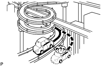


    10. I100071
    11. When the vehicle makes a continuous turn (e.g. 360, 720, 1080 degrees), the current vehicle position mark may deviate from the correct position.


    12. I100072
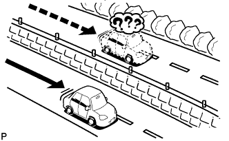
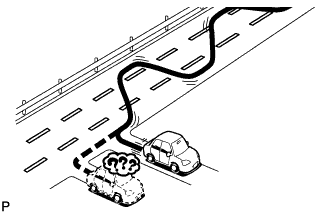
    13. When the vehicle moves erratically, such as constant lane changes, the current vehicle position mark may deviate from the correct position.


    14. E106418
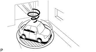
    15. When the power switch is turned to on (ACC or IG) on a turntable before parking, the current vehicle position mark may not indicate the correct direction. The same will occur when the vehicle comes out of the parking garage.


    16. I100074
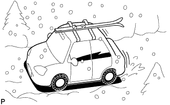
    17. When the vehicle travels on a snowy road or a mountain path with tire chains installed or using a spare tire, the current vehicle position mark may deviate from the correct position.
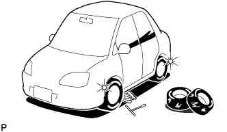


    18. I100075
    19. When the tires are changed, the current vehicle position mark may deviate from the correct position.

      HINT:
      1. A change in tire diameter may cause a speed sensor error.
      2. Performing "tire change" in calibration mode will allow the system to correct the current vehicle position faster.


MULTI-DISPLAY OPERATION CHECK

NOTICE:
  1. Before performing the multi-display operation check, check for obstacles or protrusions which may interrupt opening/closing of the display and foreign objects stuck in moving parts or the multi-display switch. Remove any obstacles or foreign objects.
  2. Do not interfere with the multi-display while it is moving.

HINT:
The multi-display can be operated using the multi-display switch.


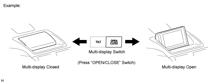
  1. Open/Close Operation


    E210258E02


    1. Press the "OPEN/CLOSE" switch of the multi-display switch and check that the multi-display opens and closes properly.

      HINT:
      1. When the multi-display is open, turning the power switch off causes the multi-display to close.
      2. When the power switch is turned on (ACC) again, the multi-display will open.
      3. Even when the power switch is turned off with the multi-display closed, the multi-display will open the next time the power switch is turned on (ACC).
      4. When navigation system DTCs are not stored, no faults are present in the remote touch, AVC-LAN communication line or MOST communication line, the power switch is on (ACC) and the multi-display is closed, pressing the "MAP" or "MENU" switch on the remote touch causes the multi-display to open.


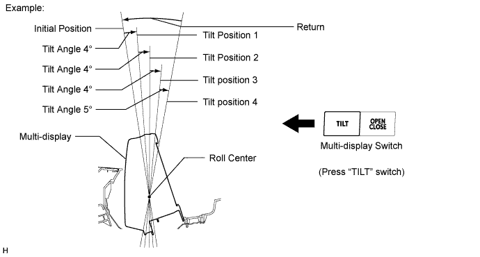
  2. Tilt Operation


    E210259E02


    1. When the multi-display is open, press the "TILT" switch of the multi-display switch and check that the multi-display tilts properly.

      HINT:
      1. The multi-display tilts to 3 different angles from the initial position at time of opening.
      2. When the multi-display is at tilt position 3, pressing the "TILT" switch causes the display to return to the initial position.
      3. The tilt position of the multi-display at the time it was closed is stored in the display module board. The next time the multi-display opens, it automatically returns to the stored tilt position.


REMOTE TOUCH INITIAL CHECK

NOTICE:
  1. Before performing the initial check, check that there are no foreign objects that will interfere with remote touch switch knob operation and that the knob is not stuck.
  2. To avoid interruption of remote touch switch knob operation, do not touch the knob during the initial check.

HINT:
  1. The remote touch performs initialization of its knob position at the time the vehicle is started and turned off.
  2. When remote touch switch knob position initialization fails, DTC B1581 will be stored.

  1. Move the remote touch switch knob to a position other than the center and turn the power switch on (ACC).

  2. Check that the remote touch switch knob moves automatically to the center of the movable area.

    HINT:
    1. Initialization of the remote touch switch knob position is complete when the knob moves to the center of the movable area.
    2. If remote touch switch knob position initialization fails, remote touch switch knob operation and pointer movement on the screen will not match.
    3. If the remote touch switch knob does not move to the center of the movable area within 10 seconds because of foreign objects or the knob being stuck, the remote touch will stop operating.
    4. When the foreign object is removed or the remote touch switch knob is freed, and the knob position changes, the knob moves to the center of the movable area and completes its initialization.
    5. The remote touch will repeatedly try to initialize itself until initialization has been completed, except when a built-in motor has a malfunction.

  3. Move the remote touch switch knob to a position other than the center and turn the power switch off.

  4. Check that the remote touch switch knob automatically moves to the center of the movable area.

    HINT:
    1. Initialization of the remote touch switch knob position is complete when the knob moves to the center of the movable area.
    2. If the remote touch switch knob does not move to the center of the movable area within 3 seconds because of foreign objects or the knob being stuck, the remote touch will stop operating. In this case, initialization of the knob position will not complete, but DTC B1581 will not be stored.


REMOTE TOUCH SELF CHECK

NOTICE:
  1. Before performing the remote touch self check, check that there are no foreign objects that would interfere with remote touch switch knob operation and that the knob is not stuck.
  2. To avoid interruption of remote touch switch knob operation, do not touch the knob unless instructed in the steps.

HINT:
The following checks can be done via the self check:
  1. DTC check for the remote touch
  2. Switch illumination check
  3. Remote touch switch knob position recognition check
  4. Switch operation check
  5. Remote touch switch knob feedback force check


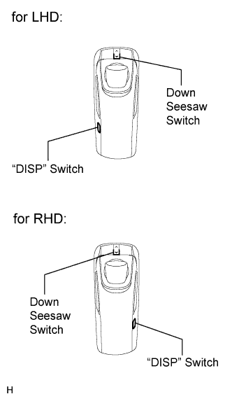
    E176741E01
  1. Activate Self Check Mode

    1. Turn the power switch on (ACC) with the "DISP" switch and the down seesaw switch pressed to activate self check mode.


  2. Switch Illumination Check and DTC Check
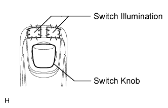


      E181064E01
    1. Check that the remote touch switch knob automatically moves to the center of the movable area and that the "MAP/VOICE" and "MENU" switch illumination turns on.
      HINT:
      1. If the remote touch switch knob does not automatically move to the center of the movable area, DTC B1581 is stored.
      2. When a DTC is stored as a present DTC during self check, the "MAP/VOICE" and "MENU" switch illumination blinks at 0.5-second intervals. The illumination will continue to blink until the self check is completed.
      3. The switch illumination stops blinking only when the factor that caused the remote touch switch knob malfunction (DTC B1581) disappears, allowing the knob to automatically move to the center of the movable area.


  3. E181022E01
  4. Remote Touch Switch Knob Position Recognition Check

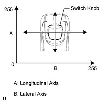
    1. Move the remote touch switch knob up, down, right and left to check that the brightness of the "MAP/VOICE" and "MENU" switch illumination changes.

      HINT:
      1. If the brightness changes according to remote touch switch knob operation, the knob position is being recognized normally.
      2. The brightness of the switch illumination changes between 0 and 100% according to the coordinates of the remote touch switch knob.
      3. The coordinates of the remote touch switch knob change between 0 and 255 for both the lateral and longitudinal axes.
      4. When the coordinates of both the lateral and longitudinal axes of the remote touch switch knob are 0, the brightness of the switch illumination becomes 0% (the lights will be off), and when the coordinates of both axes of the knob are 255, the brightness of the switch illumination becomes 100% (the switch lights will be on at full brightness).

  5. Switch Operation Check

    1. With the remote touch switch knob in the lower left position, check that pressing each switch on the remote touch turns on the "MAP/VOICE" and "MENU" switch illumination at 100% brightness.
      HINT:
      If the "MAP/VOICE" and "MENU" switch illumination turn on when a switch is pressed, the switch being pressed is operating normally.


  6. E181023E01
  7. Remote Touch Switch Knob Feedback Force Check

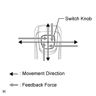
    1. Move the remote touch switch knob up, down, right and left to check that feedback force is generated.

      HINT:
      The motors built into the remote touch generate feedback force according to the direction in which the remote touch switch knob is moved.

    2. Move the pointer on the screen by operating the remote touch switch knob and check that the feedback force of the knob changes according to the screen being displayed and the pointer position.
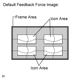
      HINT:
      1. Refer to Remote Touch Outline for further information on remote touch switch knob feedback force generated according to the screen being displayed and the pointer position (Click here).
      2. When the feedback force of the remote touch switch knob changes according to the screen being displayed and the pointer position, it means that the remote touch is receiving feedback force request signals from the display and navigation module display.

      3. E176770E01
        When the remote touch cannot receive feedback force request signals from the display and navigation module display, the remote touch generates feedback force according to the default feedback force image recorded in the remote touch (remote operation board).

  8. Finish Self Check Mode

    1. Turn the power switch off to finish self check mode.


CHECK PANEL & STEERING SWITCH

HINT:
  1. The radio receiver assembly panel switches, remote touch push switches and steering switch are checked in the following procedure.
  2. Illustrations may differ from the actual vehicle screen depending on the device settings and options. Therefore, some detailed areas may not be shown exactly the same as on the actual vehicle screen.

  1. Enter diagnostic mode (Click here).


  2. E176512
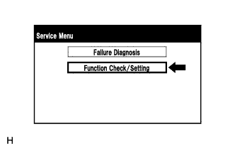
  3. Select "Function Check/Setting" from the "Service Menu" screen.
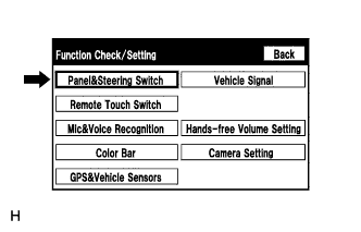


  4. E176714
  5. Select "Panel & Steering Switch" from the "Function Check/Setting" screen.


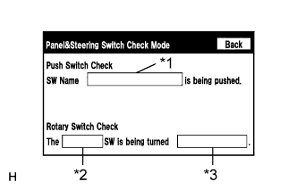
  6. Panel & Steering Switch Check Mode


      E176522E01
    1. Operate each switch and check that the switch names and condition are correctly displayed.

      Screen Description 
      Display
      Content
      *1: Name of switch being pushed
      1. Name of the pushed switch is displayed.
      2. If more than one switch is pressed, "MULTIPLE" will be displayed.
      *2: Rotary switch name
      Name of the rotary switch is displayed.
      *3: Rotary switch direction
      Direction of the rotary switch is displayed.


CHECK REMOTE TOUCH SWITCH

HINT:
  1. The remote touch switch knob and "ENTER" switches are checked in the following procedure.
  2. Illustrations may differ from the actual vehicle screen depending on the device settings and options. Therefore, some detailed areas may not be shown exactly the same as on the actual vehicle screen.

  1. Enter diagnostic mode (Click here).


  2. E176512
  3. Select "Function Check/Setting" from the "Service Menu" screen.
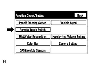


  4. E176715
  5. Select "Remote Touch Switch" from the "Function Check/Setting" screen.
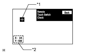


  6. E176730E04
  7. Remote Touch Switch Check

    Screen Description 
    Display
    Content
    *1: "+" mark
    Displayed at the location where the pointer is located when the "ENTER" switch on the remote touch is pressed.
    *2: Coordinates
    1. Displays the coordinates
    2. "X" and "Y" indicate the lateral and longitudinal axes
    3. Coordinates are displayed by numbers between 0 and 255 for each axis starting from the lower left of the screen

    1. While "Remote Touch Switch Check" is displayed, move the pointer to any blank area of the screen using the remote touch switch knob, and press the "ENTER" switch.

      HINT:
      1. The "+" mark is displayed at the pointer position while the "ENTER" switch is pressed.
      2. Once the "+" mark is displayed, the coordinates will be displayed.
      3. Even though the pointer is moved, the "+" mark will remain at the position where the pointer was when the "ENTER" switch was pressed.

    2. Move the pointer using the remote touch switch knob and press the "ENTER" switch again. When the location of the "+" mark is changed with the "ENTER" switch held, check that the coordinate values "X" and "Y" change between 0 and 255.


CHECK MIC & VOICE RECOGNITION

HINT:
  1. The microphone and microphone input level are checked in the following procedure.
  2. Illustrations may differ from the actual vehicle screen depending on the device settings and options. Therefore, some detailed areas may not be shown exactly the same as on the actual vehicle screen.

  1. Enter diagnostic mode (Click here).


  2. E176512
  3. Select "Function Check/Setting" from the "Service Menu" screen.
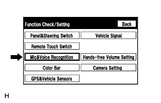


  4. E176716
  5. Select "Mic & Voice Recognition" from the "Function Check/Setting" screen.


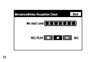
  6. Microphone & Voice Recognition Check


      E187218
    1. When speaking into the microphone, check that the microphone input level meter changes according to the input level.

    2. Select the recording switch and perform voice recording.

      HINT:
      Select the recording switch with the blower motor of the air conditioning system stopped. If an outlet of the air conditioning system is facing the microphone, noise may be recorded.

    3. Check that the recording indicator remains on while recording and that the recording can be played normally.

      HINT:
      1. For details of this function, refer to Diagnosis Display Detailed Description in System Description (Click here).
      2. This function is controlled by the display and navigation module display (built-in navigation ECU).


CHECK COLOR BAR

HINT:
  1. The display color on the screen is checked in the following procedure.
  2. Illustrations may differ from the actual vehicle screen depending on the device settings and options. Therefore, some detailed areas may not be shown exactly the same as on the actual vehicle screen.

  1. Enter diagnostic mode (Click here).


  2. E176512
  3. Select "Function Check/Setting" from the "Service Menu" screen.
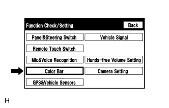


  4. E176717
  5. Select "Color Bar" from the "Function Check/Setting" screen.


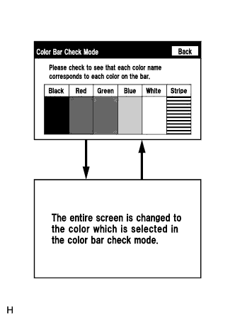
  6. Color Bar Check Mode


      E176520
    1. Select a color bar from the "Color Bar Check Mode" screen.

    2. Check the display color.

      HINT:
      1. The entire screen turns to the color or stripe selected.
      2. Touching the display will return to the "Color Bar Check Mode" screen.


CHECK GPS & VEHICLE SENSORS

HINT:
  1. GPS information, vehicle signals and sensor signals are checked in the following procedure.
  2. Illustrations may differ from the actual vehicle screen depending on the device settings and options. Therefore, some detailed areas may not be shown exactly the same as on the actual vehicle screen.

  1. Enter diagnostic mode (Click here).


  2. E176512
  3. Select "Function Check/Setting" from the "Service Menu" screen.
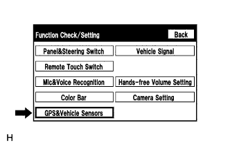


  4. E176718
  5. Select "GPS & Vehicle Sensors" from the "Function Check/Setting" screen.


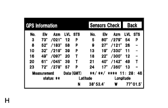
  6. GPS Information


      E187330
    1. When "GPS Information screen" is displayed, check the GPS conditions.

      HINT:
      1. This screen is updated once per second when input signals to the vehicle are changed.
      2. For details of this function, refer to Diagnosis Display Detailed Description in System Description (Click here).

  7. Select "Sensors Check" from the "GPS information" screen.


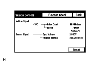
  8. Vehicle Sensors


      E176525
    1. Check all the signals and sensors when vehicle signal information is displayed.

      HINT:
      1. This screen is updated once per second when input signals to the vehicle are changed.
      2. This screen displays vehicle signals input to the display and navigation module display (built-in navigation ECU).
      3. For details of this function, refer to Diagnosis Display Detailed Description in System Description (Click here).


CHECK VEHICLE SIGNALS

HINT:
  1. Vehicle signals received by the display and navigation module display are checked in the following procedure.
  2. Illustrations may differ from the actual vehicle screen depending on the device settings and options. Therefore, some detailed areas may not be shown exactly the same as on the actual vehicle screen.

  1. Enter diagnostic mode (Click here).


  2. E176512
  3. Select "Function Check/Setting" from the "Service Menu" screen.
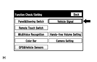


  4. E176719
  5. Select "Vehicle Signal" from the "Function Check/Setting" screen.


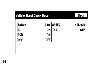
  6. Vehicle Signal Check Mode


      E176523
    1. When the "Vehicle Signal Check Mode" screen is displayed, check all the vehicle signal conditions.

      HINT:
      1. Only conditions having inputs are displayed.
      2. This screen displays vehicle signals input to the display and navigation module display (built-in navigation ECU).
      3. For details of this function, refer to Diagnosis Display Detailed Description in System Description (Click here).


CHECK HANDS-FREE VOLUME SETTING

HINT:
  1. The hands-free volume of a "Bluetooth" compatible phone can be adjusted using the following procedure.
  2. Illustrations may differ from the actual vehicle screen depending on the device settings and options. Therefore, some detailed areas may not be shown exactly the same as on the actual vehicle screen.

  1. Enter diagnostic mode (Click here).


  2. E176512
  3. Select "Function Check/Setting" from the "Service Menu" screen.
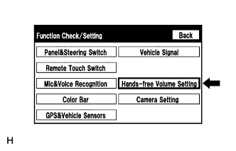


  4. E176720
  5. Select "Hands-free Volume Setting" from the "Function Check/Setting" screen.


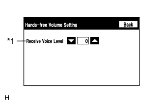
  6. Hands-free Volume Setting


      E176527E01
    1. Check the hands-free volume level.

      Screen Description 
      Display
      Content
      *1: Receive voice level adjustment
      Adjusts voice level received from "Bluetooth" compatible phones

      NOTICE:
      Sound quality may deteriorate when the receive voice level is changed more than necessary. For this reason, check that the receive voice quality is still acceptable after changing this setting.


CHECK CAMERA SETTING

HINT:
  1. Vehicle signals received by the parking assist ECU are checked in the following procedure.
  2. Illustrations may differ from the actual vehicle screen depending on the device settings and options. Therefore, some detailed areas may not be shown exactly the same as on the actual vehicle screen.

  1. Enter diagnostic mode (Click here).


  2. E176512
  3. Select "Function Check/Setting" from the "Service Menu" screen.
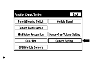


  4. E181115
  5. Select "Camera Setting" from the "Function Check/Setting" screen.
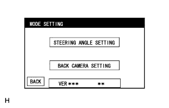


  6. E187249
  7. MODE SETTING

    HINT:
    Refer to the parking assist monitor system for further information (Click here).