DTC P0C73-776 Motor Electronics Coolant Pump "A" Control Performance |
| DTC No. | INF Code | DTC Detection Condition | Trouble Area |
| P0C73 | 776 | A speed or intermittent stop malfunction occurs in the inverter water pump assembly. |
|
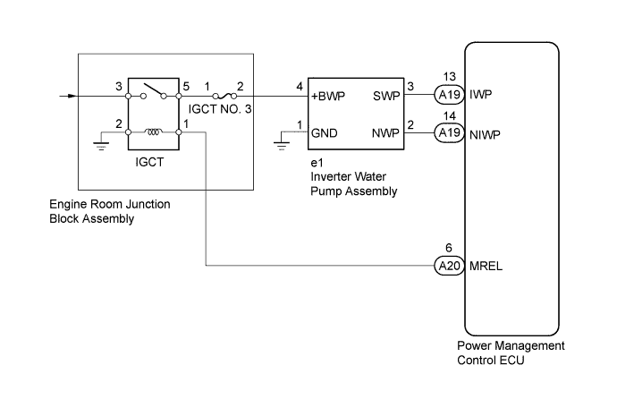
| 1.CHECK QUANTITY OF HV COOLANT |
Check the coolant level in the inverter reserve tank.
Check for coolant leaks.
| Result | Proceed to |
| Coolant leaks are not evident. A sufficient amount of coolant remains in the inverter reserve tank. | A |
| Coolant leaks are not evident. No coolant remains in the inverter reserve tank. | B |
| Coolant leaks are evident. | C |
|
| ||||
|
| ||||
| A | |
 |
| 2.CHECK COOLANT HOSE |
Check if the hoses of the cooling system are kinked or clogged.
|
| ||||
| OK | |
|
| 3.CHECK INVERTER WATER PUMP ASSEMBLY |
Connect the intelligent tester to the DLC3.
Turn the power switch on (IG).
Enter the following menus: Powertrain / Hybrid Control / Data List.
Select Inverter W/P Revolution in the Data List.
Read the Data List.
| Tester Display | Specified Condition |
| Inverter W/P Revolution | 625 rpm or less |
Turn the power switch off.
|
| ||||
| OK | |
|
| 4.PERFORM ACTIVE TEST USING INTELLIGENT TESTER (ACTIVATE THE WATER PUMP) |
Connect the intelligent tester to the DLC3.
Turn the power switch on (IG).
Enter the following menus: Powertrain / Hybrid Control / Active Test / Activate the Water Pump.
Select Inverter W/P Revolution in the Data List.
While performing the "Activate the Water Pump" Active Test, check Inverter W/P Revolution in the Data List.
| Tester Display | Specified Condition |
| Inverter W/P Revolution | 2250 to 5625 rpm |
Turn the power switch off.
|
| ||||
| OK | |
|
| 5.CHECK HV COOLANT (CHECK FOR CONDITIONS THAT MAY HAVE CAUSED FREEZING) |
Connect the intelligent tester to the DLC3.
Turn the power switch on (IG).
Read the freeze frame data Ambient Temperature using the intelligent tester.
Check if the freeze frame data Ambient Temperature is below freezing.
| Result | Proceed to |
| Ambient Temperature value is above freezing temperature of the HV coolant | A |
| Ambient Temperature value is below freezing temperature of the HV coolant | B |
Turn the power switch off.
|
| ||||
| A | ||
 | ||
| ||
| 6.ADD HV COOLANT |
Add coolant up to the high level in the reserve tank.
|
| ||||
| 7.INSPECT FOR COOLANT LEAK |
Diagnose and repair the coolant leak.
|
| ||||
| 8.CORRECT THE PROBLEM |
Correct the coolant hose.
|
| ||||
| 9.CHECK CONNECTOR CONNECTION CONDITION (POWER MANAGEMENT CONTROL ECU CONNECTOR) |
Check the connections of the power management control ECU connectors.
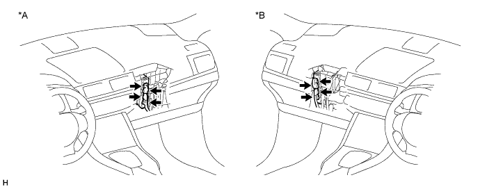
| *A | for LHD | *B | for RHD |
|
| ||||
| OK | |
|
| 10.CHECK CONNECTOR CONNECTION CONDITION (INVERTER WATER PUMP ASSEMBLY CONNECTOR) |
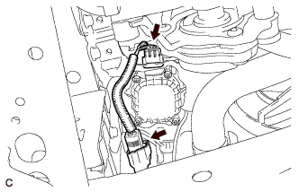 |
Check the connection of the inverter water pump assembly connector.
|
| ||||
| OK | |
|
| 11.CHECK HARNESS AND CONNECTOR (POWER MANAGEMENT CONTROL ECU - INVERTER WATER PUMP ASSEMBLY) |
Disconnect connector A19 from the power management control ECU.
Disconnect connector e1 from the inverter water pump assembly.
Measure the resistance according to the value(s) in the table below.
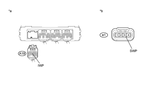
| *a | Rear view of wire harness connector (to Power Management Control ECU) | *b | Front view of wire harness connector (to Inverter Water Pump Assembly) |
| Tester Connection | Switch Condition | Specified Condition |
| e1-3 (SWP) - A19-13 (IWP) | Power switch off | Below 1 Ω |
| Tester Connection | Switch Condition | Specified Condition |
| e1-3 (SWP) or A19-13 (IWP) - Body ground and other terminals | Power switch off | 10 kΩ or higher |
Connect the power management control ECU connector.
Connect the inverter water pump assembly connector.
|
| ||||
| OK | |
|
| 12.READ VALUE USING INTELLIGENT TESTER (INVERTER W/P REVOLUTION) |
Connect the intelligent tester to the DLC3.
Turn the power switch on (IG).
Enter the following menus: Powertrain / Hybrid Control / ECU Data List.
Select Inverter W/P Revolution in the Data List.
Disconnect connector e1 from the inverter water pump assembly.
Read the Data List.
| Tester Display | Specified Condition |
| Inverter W/P Revolution | 125 rpm or less |
Connect the inverter water pump assembly connector.
Turn the power switch off.
|
| ||||
| OK | |
|
| 13.CHECK HARNESS AND CONNECTOR (POWER MANAGEMENT CONTROL ECU - INVERTER WATER PUMP ASSEMBLY) |
Disconnect connector A19 from the power management control ECU.
Turn the power switch on (IG).
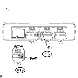 |
Measure the voltage according to the value(s) in the table below.
| *a | Rear view of wire harness connector (to Power Management Control ECU) |
| Tester Connection | Switch Condition | Specified Condition |
| A19-13 (IWP) - H3-6 (E1) | Power switch on (IG) | 11 to 14 V |
Turn the power switch off.
Connect the power management control ECU connector.
|
| ||||
| OK | |
|
| 14.CHECK POWER MANAGEMENT CONTROL ECU |
Turn the power switch on (IG).
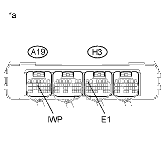 |
While turning the power switch on (IG), check the waveform between the power management control ECU terminals.
| *a | Component with Harness Connected (Power Management Control ECU) |
Turn the power switch off.
|
| ||||
| OK | ||
| ||
| ||
| 15.CONNECT SECURELY |
Connect the power management control ECU connectors securely.
|
| ||||
| 16.CONNECT SECURELY |
Connect the inverter water pump assembly connector securely.
|
| ||||
| 17.REPAIR OR REPLACE HARNESS OR CONNECTOR |
Repair or replace the wire harness or connector.
|
| ||||
| 18.REPLACE POWER MANAGEMENT CONTROL ECU |
Replace the power management control ECU (Click here).
|
| ||||
| 19.REPLACE POWER MANAGEMENT CONTROL ECU |
Replace the power management control ECU (Click here).
|
| ||||
| 20.REPLACE HV COOLANT |
Replace the HV coolant with coolant having an appropriate concentration (appropriate freeze point) for the vehicle usage conditions (Click here).
| NEXT | |
|
| 21.CHECK INVERTER WATER PUMP ASSEMBLY |
Perform a road test and check that DTCs are not stored.
|
| ||||
| OK | ||
| ||
| ||


