DTC P314A-828 Inverter Coolant Pump Speed Signal |
| DTC No. | INF Code | DTC Detection Condition | Trouble Area |
| P314A | 828 | Open in the inverter water pump assembly speed signal line or inverter water pump assembly power source circuit. |
|
| 1.PERFORM ACTIVE TEST USING INTELLIGENT TESTER (ACTIVATE THE WATER PUMP) |
Connect the intelligent tester to the DLC3.
Turn the power switch on (IG).
Enter the following menus: Powertrain / Hybrid Control / Active Test / Activate the Water Pump.
Perform the Activate the Water Pump Active Test.
Touch the inverter water pump assembly and check that it is operating (vibrating).
Turn the power switch off.
|
| ||||
| OK | |
 |
| 2.CHECK CONNECTOR CONNECTION CONDITION (POWER MANAGEMENT CONTROL ECU CONNECTOR) |
Check the connections of the power management control ECU connectors.
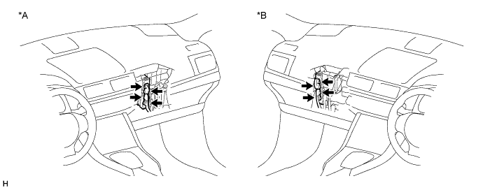
| *A | for LHD | *B | for RHD |
|
| ||||
| OK | |
|
| 3.CHECK CONNECTOR CONNECTION CONDITION (INVERTER WATER PUMP ASSEMBLY CONNECTOR) |
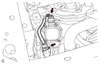 |
Check the connection of the inverter water pump assembly connector.
|
| ||||
| OK | |
|
| 4.CHECK HARNESS AND CONNECTOR (POWER MANAGEMENT CONTROL ECU - INVERTER WATER PUMP ASSEMBLY) |
Disconnect connector A19 from the power management control ECU.
Disconnect connector e1 from the inverter water pump assembly.
Measure the resistance according to the value(s) in the table below.
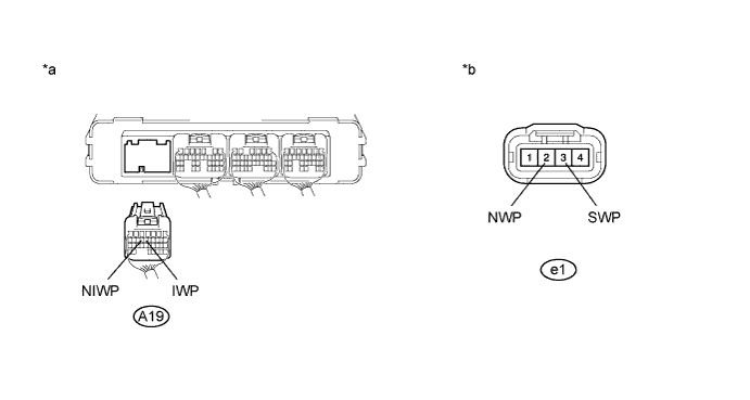
| *a | Rear view of wire harness connector (to Power Management Control ECU) | *b | Front view of wire harness connector (to Inverter Water Pump Assembly) |
| Tester Connection | Switch Condition | Specified Condition |
| e1-2 (NWP) - A19-14 (NIWP) | Power switch off | Below 1 Ω |
| e1-3 (SWP) - A19-13 (IWP) | Power switch off | Below 1 Ω |
| e1-2 (NWP) or A19-14 (NIWP) -Body ground and other terminals | Power switch off | 10 kΩ or higher |
| e1-3 (SWP) or A19-13 (IWP) - Body ground and other terminals | Power switch off | 10 kΩ or higher |
Connect the power management control ECU connector.
Connect the inverter water pump assembly connector.
|
| ||||
| OK | |
|
| 5.CHECK POWER MANAGEMENT CONTROL ECU |
Disconnect connector e1 from the inverter water pump assembly.
Turn the power switch on (IG).
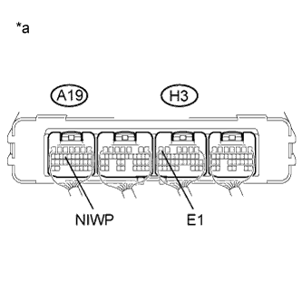 |
Measure the voltage according to the value(s) in the table below.
| Tester Connection | Switch Condition | Specified Condition |
| A19-14 (NIWP) - H3-6 (E1) | Power switch on (IG) | 11 to 14 V |
| *a | Component with harness connected (to Power Management Control ECU) |
Turn the power switch off.
Connect the inverter water pump assembly connector.
|
| ||||
| OK | |
|
| 6.PERFORM ACTIVE TEST USING INTELLIGENT TESTER (ACTIVATE THE WATER PUMP) |
Connect the intelligent tester to the DLC3.
Turn the power switch on (IG).
Enter the following menus: Powertrain / Hybrid Control / Active Test / Activate the Water Pump.
Select Inverter W/P Revolution in the Data List.
While performing the "Activate the Water Pump" Active Test, check Inverter W/P Revolution in the Data List.
| Data List Item | Specified Condition |
| Inverter W/P Revolution | 125 rpm or higher |
Turn the power switch off.
|
| ||||
| OK | ||
 | ||
| ||
| 7.CHECK FUSE (IGCT NO. 3) |
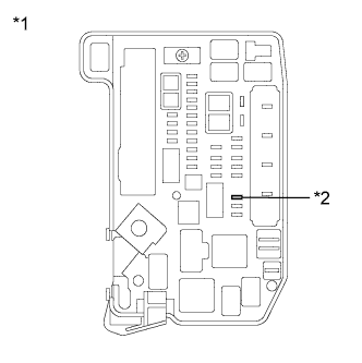 |
Remove the IGCT NO. 3 fuse from the engine room junction block assembly.
Measure the resistance according to the value(s) in the table below.
| Tester Connection | Condition | Specified Condition |
| IGCT NO. 3 fuse | Always | Below 1Ω |
| *1 | Engine Room Junction Block Assembly |
| *2 | IGCT NO. 3 Fuse |
Install the IGCT NO. 3 fuse.
|
| ||||
| OK | |
|
| 8.CHECK CONNECTOR CONNECTION CONDITION (INVERTER WATER PUMP ASSEMBLY CONNECTOR) |
|
Check the connection of the inverter water pump assembly connector.
|
| ||||
| OK | |
|
| 9.CHECK HARNESS AND CONNECTOR (INVERTER WATER PUMP ASSEMBLY CIRCUIT) |
Remove the IGCT NO. 3 fuse from the engine room junction block assembly.
Remove the IGCT relay from the engine room junction block assembly.
Disconnect connector A19 from the power management control ECU.
Disconnect connector e1 from the inverter water pump assembly.
Measure the resistance according to the value(s) in the table below.
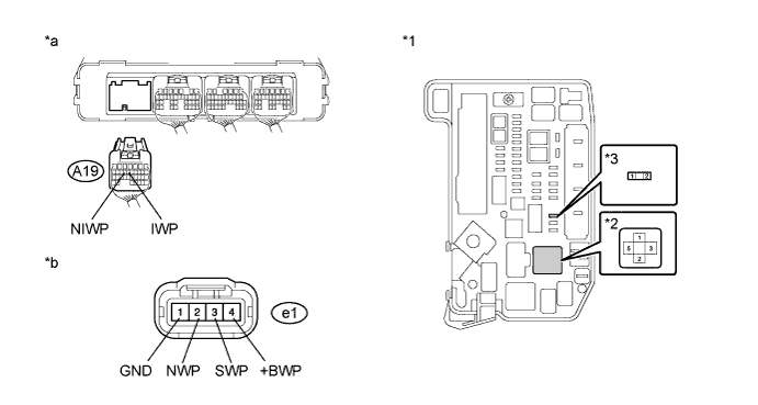
| *1 | Engine Room Junction Block Assembly | *2 | IGCT Relay |
| *3 | IGCT NO. 3 Fuse | - | - |
| *a | Rear view of wire harness connector (to Power Management Control ECU) | *b | Front view of wire harness connector (to Inverter Water Pump Assembly) |
| Tester Connection | Switch Condition | Specified Condition |
| 2 (IGCT NO. 3 fuse) - e1- 4 (+BWP) | Power switch off | Below 1Ω |
| 1 (IGCT NO. 3 fuse) - 5 (IGCT relay) | Power switch off | Below 1Ω |
| e1-1 (GND) - Body ground | Power switch off | Below 1Ω |
| e1-2 (NWP) - A19-14 (NIWP) | Power switch off | Below 1Ω |
| e1-3 (SWP) - A19-13 (IWP) | Power switch off | Below 1Ω |
| 2 (IGCT NO. 3 fuse) or e1-4 (+BWP) - Body ground and other terminals | Power switch off | 10 kΩ or higher |
| 1 (IGCT NO. 3 fuse) or 5 (IGCT relay) - Body ground and other terminals | Power switch off | 10 kΩ or higher |
| e1-2 (NWP) or A19-14 (NIWP) - Body ground and other terminals | Power switch off | 10 kΩ or higher |
| e1-3 (SWP) or A19-13 (IWP) - Body ground and other terminals | Power switch off | 10 kΩ or higher |
Install the IGCT NO. 3 fuse.
Install the IGCT relay.
Connect the power management control ECU connector.
Connect the inverter water pump assembly connector.
|
| ||||
| OK | ||
| ||
| ||
| 10.CHECK CONNECTOR CONNECTION CONDITION (INVERTER WATER PUMP ASSEMBLY CONNECTOR) |
|
Check the connection of the inverter water pump assembly connector.
|
| ||||
| OK | |
|
| 11.CHECK HARNESS AND CONNECTOR (INVERTER WATER PUMP ASSEMBLY CIRCUIT) |
Remove the IGCT NO. 3 fuse from the engine room junction block assembly.
Disconnect connector e1 from the inverter water pump assembly.
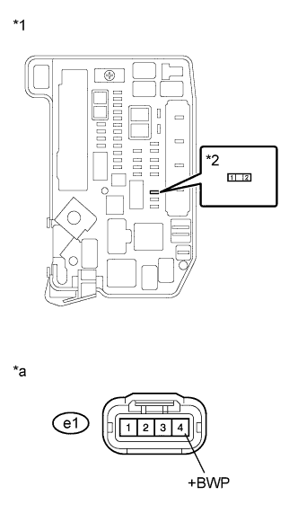 |
Measure the resistance according to the value(s) in the table below.
| Tester Connection | Switch Condition | Specified Condition |
| 2 (IGCT NO. 3 fuse) or e1-4 (+BWP) - Body ground and other terminals | Power switch off | 10 kΩ or higher |
| *1 | Engine Room Junction Block Assembly |
| *2 | IGCT NO. 3 Fuse |
| *a | Front view of wire harness connector (to Inverter Water Pump Assembly) |
Install the IGCT NO. 3 fuse.
Connect the inverter water pump assembly connector.
|
| ||||
| OK | |
|
| 12.REPLACE INVERTER WATER PUMP ASSEMBLY |
Replace the inverter water pump assembly (Click here).
| NEXT | ||
| ||
| ||
| 13.CONNECT SECURELY |
Connect the inverter water pump assembly connector securely.
| NEXT | ||
| ||
| ||
| 14.REPAIR OR REPLACE HARNESS OR CONNECTOR |
Repair or replace the wire harness or connector.
| NEXT | ||
| ||
| ||


