REAR UPPER ARM > INSTALLATION

for Preparation Click here


HINT:
  1. Use the same procedure for the RH side and LH side.
  2. The procedure listed below is for the LH side.


1. TEMPORARILY TIGHTEN REAR UPPER CONTROL ARM ASSEMBLY


    C234177
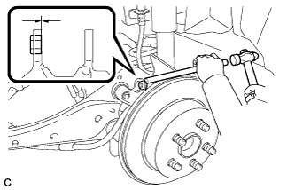
  1. Using a brass bar and a hammer, push out the bushing until it is positioned as shown in the illustration.

    HINT:
    Pushing out the bushing makes it easier to install the rear upper control arm assembly.

  1. Use a jack and wooden block to keep the rear No. 2 suspension arm assembly level.
    CAUTION:
    Do not jack up the rear No. 2 suspension arm assembly too high as the vehicle may fall.

    NOTICE:
    1. When jacking up the rear No. 2 suspension arm assembly, be sure to jack it up slowly.
    2. Make sure to perform this operation with the vehicle kept as low as possible.


    C211900E01
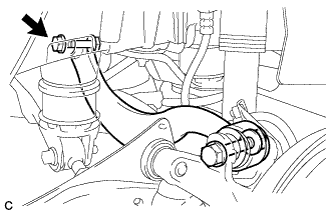
  1. Temporarily tighten the rear upper control arm assembly to the rear suspension member sub-assembly with the bolt (A) and nut.
    Text in Illustration 
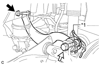
    *1
    No. 2 Flexible Hose Bracket
    V100135
    Bolt (A)
    V100136
    Bolt (B)

    NOTICE:
    1. Since a stopper nut is used, turn the bolt.
    2. Insert the bolt with the threaded end facing the rear of the vehicle.

  1. Fully tighten the rear upper control arm assembly and No. 2 flexible hose bracket to the rear axle assembly with the bolt (B) and nut.

    Torque:
    90 N*m{ 918 kgf*cm , 66 ft.*lbf }

    NOTICE:
    1. Since a stopper nut is used, turn the bolt.
    2. Insert the bolt with the threaded end facing the rear of the vehicle.


2. STABILIZE SUSPENSION


    C234403E01
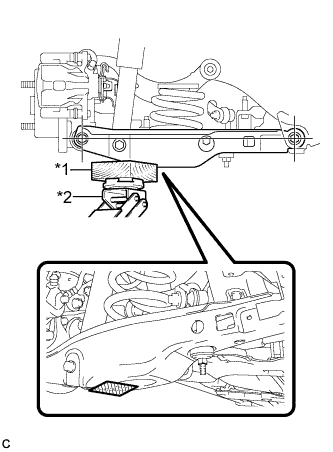
  1. Using a jack and wooden block as shown in the illustration, jack up the rear No. 2 suspension arm assembly to keep it level so that the suspension is positioned at the vehicle standard height position (position for final tightening of the suspension).
    Text in Illustration 
    *1
    Wooden Block
    *2
    Jack
    V100155
    Wooden Block placement location

    CAUTION:
    Do not jack up the rear No. 2 suspension arm assembly too high as the vehicle may fall.

    NOTICE:
    1. When jacking up the rear No. 2 suspension arm assembly, be sure to jack it up slowly.
    2. Make sure to perform this operation with the vehicle kept as low as possible.

    HINT:
    1. If the rear No. 2 suspension arm assembly cannot be positioned within the specification even when the rear No. 2 suspension arm assembly is jacked up, apply additional load such as by placing a weight in the luggage compartment.
    2. This procedure duplicates standard vehicle height conditions.
    3. Use the same procedure for the RH side and LH side.


3. FULLY TIGHTEN REAR UPPER CONTROL ARM ASSEMBLY


    C211901
  1. Fully tighten the bolt.

    Torque:
    90 N*m{ 918 kgf*cm , 66 ft.*lbf }

    NOTICE:
    1. Since a stopper nut is used, turn the bolt.
    2. Make sure that the rear No. 2 suspension arm assembly remains level when fully tightening the bolt.


4. INSTALL REAR FLOOR SIDE MEMBER COVER (w/ Floor Under Cover)
  1. for LH Side:

    1. Install the rear floor side member cover LH with the 2 bolts, nut and 2 clips.

  1. for RH Side:

    1. Install the rear floor side member cover RH with the bolt, nut and 2 clips.


5. INSTALL REAR SUSPENSION ARM COVER
  1. Insert the 2 claws of the rear suspension arm cover into the rear No. 2 suspension arm assembly.

  1. Install the rear suspension arm cover with the 2 bolts.

    Torque:
    12 N*m{ 122 kgf*cm , 9 ft.*lbf }

    NOTICE:
    Make sure that the 2 claws of the rear suspension arm cover are inserted.


6. INSTALL REAR WHEEL

Torque:
103 N*m{ 1050 kgf*cm , 76 ft.*lbf }


7. INSPECT AND ADJUST REAR WHEEL ALIGNMENT
(Click here)