REAR LOWER ARM > REMOVAL |
| 1. REMOVE REAR WHEEL |
| 2. REMOVE REAR SUSPENSION ARM COVER |
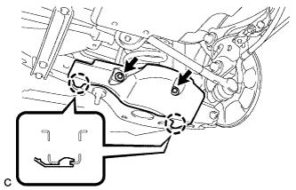 |
Remove the 2 bolts and disengage the 2 claws to remove the rear suspension arm cover from the rear No. 2 suspension arm assembly.
| 3. REMOVE REAR FLOOR SIDE MEMBER COVER (w/ Floor Under Cover) |
for LH Side:
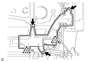 |
Remove the 2 bolts, nut and clip.
Disengage the clip and remove the rear floor side member cover LH.
for RH Side:
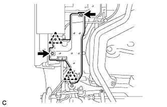 |
Remove the bolt and nut.
Disengage the 2 clips and remove the rear floor side member cover RH.
| 4. REMOVE REAR NO. 1 SUSPENSION ARM ASSEMBLY |
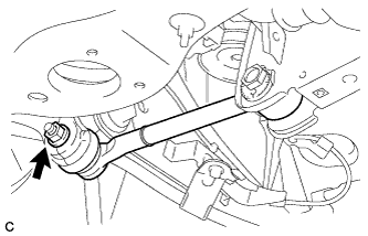 |
Remove the nut.
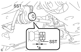 |
Install 2 spacers (SST spacer B) as shown in the illustration.
| *a | 1 mm or more |
Using SST, separate the rear No. 1 suspension arm assembly from the rear axle assembly as shown in the illustration.
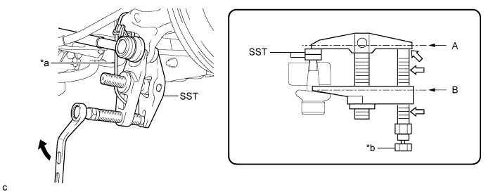
| *a | Tie the string without any slack. | *b | Place a wrench here. |
 | Turn |  | Grease |
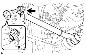 |
Place matchmarks on the No. 2 camber adjust cam, rear suspension toe adjust cam sub-assembly and rear suspension member sub-assembly.
| *a | Matchmarks |
Remove the nut, No. 2 camber adjust cam, rear suspension toe adjust cam sub-assembly and rear No. 1 suspension arm assembly.
| 5. REMOVE REAR HEIGHT CONTROL SENSOR SUB-ASSEMBLY (w/ Height Control Sensor) |
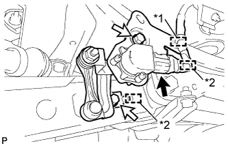 |
Disengage the clamp.
Disconnect the connector.
| *1 | Clamp |
| *2 | Guide |
Remove the 2 bolts.
Disengage the 2 guides and remove the rear height control sensor sub-assembly.
| 6. REMOVE REAR STABILIZER LINK ASSEMBLY |
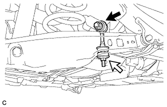 |
Remove the nut (A) and separate the rear stabilizer link assembly LH from the rear stabilizer bar.
| Nut (A) |
| Nut (B) |
Remove the nut (B), rear stabilizer link assembly LH and 2 rear stabilizer cushions.
| 7. REMOVE REAR SUSPENSION MEMBER BRACE |
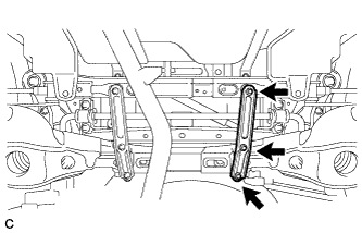 |
Remove the 3 bolts and rear suspension member brace LH from the rear suspension member sub-assembly.
| 8. REMOVE REAR COIL SPRING |
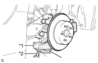 |
Support the rear axle assembly with a jack using a wooden block as shown in the illustration.
| *1 | Wooden Block |
| *2 | Jack |
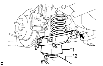 |
Support the rear No. 2 suspension arm assembly using a jack and wooden block.
| *1 | Wooden Block |
| *2 | Jack |
| Bolt (A) |
| Bolt (B) |
 | Bolt (C) |
Loosen the bolt (A).
Remove the bolt (B) and nut, and separate the rear No. 2 suspension arm assembly from the rear axle assembly.
Remove the bolt (C) and nut, and then slowly lower the rear No. 2 suspension arm assembly, and remove the rear coil spring.
| 9. REMOVE REAR UPPER COIL SPRING INSULATOR |
Remove the rear upper coil spring insulator.
| 10. REMOVE REAR LOWER COIL SPRING INSULATOR |
Remove the rear lower coil spring insulator.
| 11. REMOVE REAR NO. 2 SUSPENSION ARM ASSEMBLY |
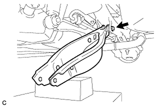 |
Remove the bolt, nut and rear No. 2 suspension arm assembly from the rear suspension member sub-assembly.
