ENGINE UNIT > REMOVAL |
| 1. INSTALL ENGINE STAND |
Install the engine onto an engine stand with the bolts.
| 2. REMOVE ENGINE HANGERS |
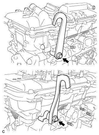 |
Remove the 2 bolts and 2 engine hangers.
| 3. REMOVE THROTTLE BODY ASSEMBLY |
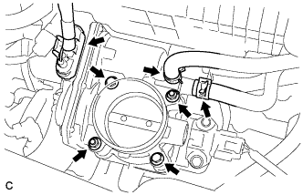 |
Disconnect the throttle body connector and 2 water by-pass hoses.
Remove the 2 bolts, 2 nuts and throttle body assembly.
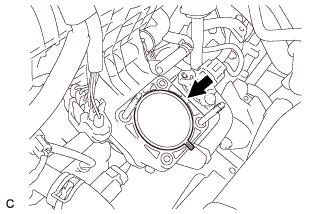 |
Remove the gasket from the intake manifold.
| 4. REMOVE ENGINE OIL LEVEL DIPSTICK GUIDE |
Remove the engine oil level dipstick.
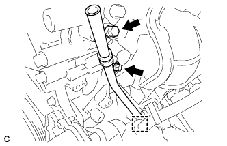 |
Remove the 2 bolts, clamp and engine oil level dipstick guide.
Remove the O-ring from the engine oil level dipstick guide.
| 5. REMOVE EGR PIPE ASSEMBLY |
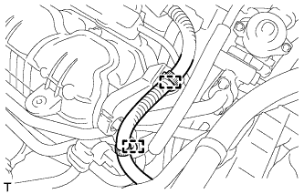 |
Disconnect the 2 wire harness clamps.
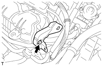 |
Remove the bolt and wire harness support.
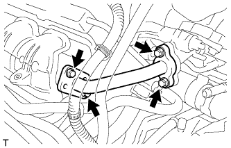 |
Remove the 4 bolts, EGR pipe assembly and 2 gaskets.
| 6. REMOVE EGR VALVE ASSEMBLY |
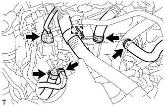 |
Disconnect the connector, wire harness clamp and 4 water hoses.
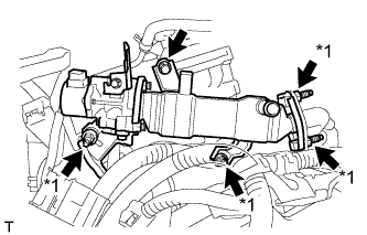 |
Remove the 4 nuts and bolt.
| *1 | Stud Bolt and Nut |
Using an E8 "TORX" socket wrench, remove the 4 stud bolts and EGR valve with cooler assembly.
Remove the gasket.
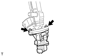 |
Remove the 2 nuts, EGR valve assembly and gasket.
| 7. REMOVE EGR WITH COOLER PIPE SUB-ASSEMBLY |
|
Disconnect the connector, wire harness clamp and 4 water hoses.
|
Remove the 4 nuts and bolt.
| *1 | Stud Bolt and Nut |
Using an E8 "TORX" socket wrench, remove the 4 stud bolts and EGR valve with cooler assembly.
Remove the gasket.
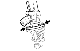 |
Remove the 2 nuts, EGR cooler sub-assembly and gasket.
| 8. REMOVE INTAKE MANIFOLD |
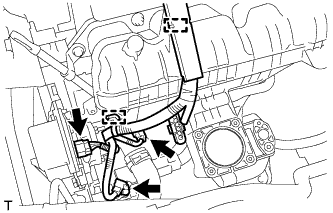 |
Disconnect the 3 connectors and 2 wire harness clamps.
Remove the engine oil level dipstick.
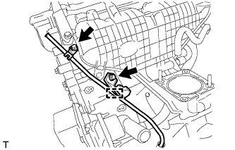 |
Disconnect the wire harness clamp, and then remove the 2 bolts and engine oil level dipstick guide sub-assembly.
Remove the O-ring from the engine oil level dipstick guide sub-assembly.
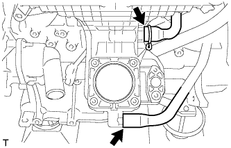 |
Disconnect the fuel vapor feed hose and ventilation hose.
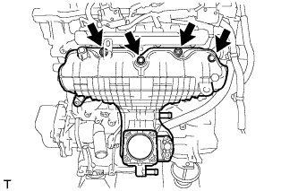 |
Remove the 2 bolts, 2 nuts and intake manifold.
Remove the No. 1 intake manifold to head gasket.
| 9. REMOVE FUEL VAPOR FEED PIPE |
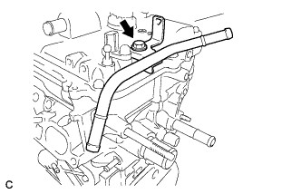 |
Remove the bolt and fuel vapor feed pipe.
| 10. REMOVE FUEL DELIVERY PIPE SUB-ASSEMBLY |
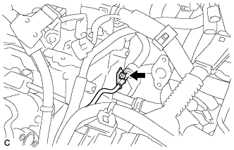 |
Remove the bolt.
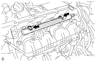 |
Remove the 2 bolts and fuel delivery pipe sub-assembly.
| 11. REMOVE NO. 1 DELIVERY PIPE SPACER |
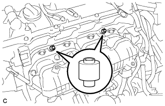 |
Remove the 2 delivery pipe spacers from the cylinder head.
| 12. REMOVE FUEL INJECTOR ASSEMBLY |
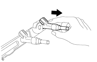 |
Pull the 4 fuel injector assemblies out of the fuel delivery pipe sub-assembly.
Remove the O-ring from each fuel injector assembly.
For reinstallation, attach a tag or label to each injector shaft.
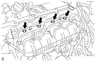 |
Remove the 4 injector vibration insulators.
| 13. REMOVE NO. 1 EXHAUST MANIFOLD HEAT INSULATOR |
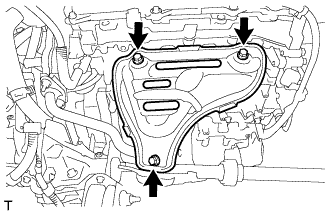 |
Remove the 3 bolts and No. 1 exhaust manifold heat insulator.
| 14. REMOVE MANIFOLD STAY |
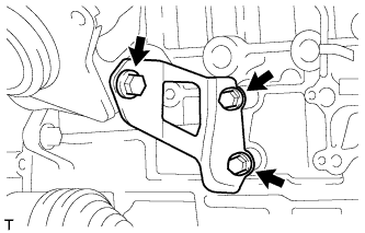 |
Remove the 3 bolts and manifold stay.
| 15. REMOVE EXHAUST MANIFOLD |
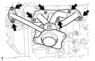 |
Remove the 7 nuts, exhaust manifold and 2 gaskets.
| 16. REMOVE VENTILATION HOSE |
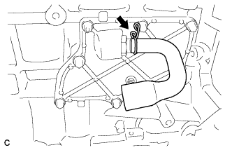 |
Remove the ventilation hose from the ventilation valve.
| 17. REMOVE IGNITION COIL ASSEMBLY |
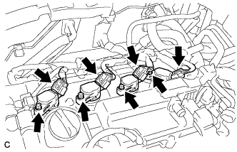 |
Disconnect the 4 ignition coil connectors.
Remove the 4 bolts and 4 ignition coils.
