DTC B27A6 Open in Rear Floor Electrical Key Oscillator Circuit |
| DTC Code | DTC Detection Condition | Trouble Area | DTC Output Confirmation Operation |
| B27A6 | An open circuit is detected in the circuit between the certification ECU (smart key ECU assembly) and No. 2 indoor electrical key antenna assembly (rear floor) (CLG6 - CLG4, CG6B - CLGB) (1 trip detection logic*). |
| Any time |
| Vehicle Condition when Malfunction Detected | Fail-safe Operation when Malfunction Detected |
When key is in rear seat area:
| - |
| DTC Code | Data List and Active Test |
| B27A6 | Key diagnostic mode can be used to perform troubleshooting |
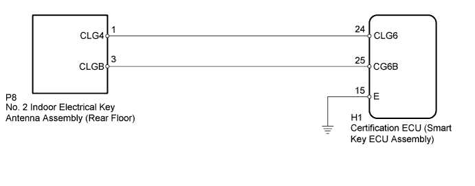
| 1.CHECK CONNECTOR CONNECTION |
Turn the power switch off.
Check that the connectors are properly connected to the certification ECU (smart key ECU assembly) and No. 2 indoor electrical key antenna assembly (rear floor).
|
| ||||
| OK | |
 |
| 2.CHECK HARNESS AND CONNECTOR (CERTIFICATION ECU - NO. 2 INDOOR ELECTRICAL KEY ANTENNA) |
Disconnect the H1 certification ECU (smart key ECU assembly) connector.
Disconnect the P8 No. 2 indoor electrical key antenna assembly (rear floor) connector.
Measure the resistance according to the value(s) in the table below.
| Tester Connection | Condition | Specified Condition |
| H1-24 (CLG6) - P8-1 (CLG4) | Always | Below 1 Ω |
| H1-25 (CG6B) - P8-3 (CLGB) | Always | Below 1 Ω |
| H1-15 (E) - Body ground | Always | Below 1 Ω |
| H1-24 (CLG6) or P8-1 (CLG4) - Body ground | Always | 10 kΩ or higher |
| H1-25 (CG6B) or P8-3 (CLGB) - Body ground | Always | 10 kΩ or higher |
|
| ||||
| OK | |
|
| 3.CHECK CERTIFICATION ECU (SMART KEY ECU ASSEMBLY) (OUTPUT TO NO. 2 INDOOR ELECTRICAL KEY ANTENNA [REAR FLOOR]) |
Connect the H1 certification ECU (smart key ECU assembly) connector.
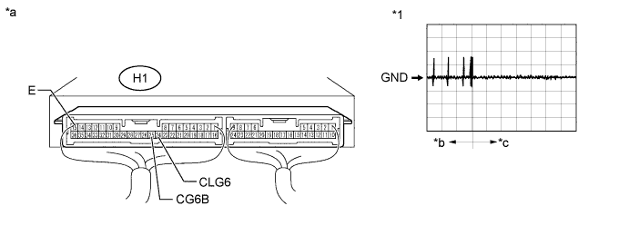
| *1 | Waveform | - | - |
| *a | Component with harness connected (Certification ECU (Smart Key ECU Assembly)) | *b | Door open |
| *c | After approximately 30 seconds from when the door is closed | - | - |
Connect the P8 No. 2 indoor electrical key antenna assembly (rear floor) connector.
Using an oscilloscope, check the waveform.
| Tester Connection | Switch Condition | Tool Setting | Specified Condition |
| H1-24 (CLG6) - H1-15 (E) | Procedure:
| 2 V/DIV., 500 ms/DIV. | Pulse generation (See waveform) |
| H1-25 (CG6B) - H1-15 (E) | Procedure:
| 2 V/DIV., 500 ms/DIV. | Pulse generation (See waveform) |
|
| ||||
| OK | |
|
| 4.REPLACE NO. 2 INDOOR ELECTRICAL KEY ANTENNA ASSEMBLY (REAR FLOOR) |
Temporarily replace the No. 2 indoor electrical key antenna assembly (rear floor) with a new or normally functioning one (Click here).
| NEXT | |
|
| 5.CLEAR DTC |
Clear the DTCs (Click here).
| NEXT | |
|
| 6.CHECK FOR DTC |
Check for DTCs (Click here).
|
| ||||
| OK | ||
 | ||
| ||

