DTC    B27A7    Open in Inside Luggage Compartment Electrical Key Oscillator Circuit

for Preparation Click here


DESCRIPTION

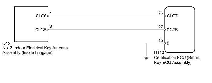
The certification ECU (smart key ECU assembly) generates a request signal and transmits the signal to the No. 3 indoor electrical key antenna assembly (inside luggage). For the No. 3 indoor electrical key antenna assembly (inside luggage) to detect when the key is inside the luggage compartment, the signal from the certification ECU (smart key ECU assembly) requesting a response from the key is transmitted inside the luggage compartment. DTC B27A7 is stored by the certification ECU (smart key ECU assembly) when an open circuit is detected between the certification ECU (smart key ECU assembly) and No. 3 indoor electrical key antenna assembly (inside luggage) (between terminals CLG7 and CLG6, or terminals CG7B and CLGB).

DTC Code
DTC Detection Condition
Trouble Area
DTC Output Confirmation Operation
B27A7
An open circuit is detected in the circuit between the certification ECU (smart key ECU assembly) and No. 3 indoor electrical key antenna assembly (inside luggage) (CLG7 - CLG6, CG7B - CLGB) (1 trip detection logic*).
  1. Wire harness or connector
  2. No. 3 indoor electrical key antenna assembly (inside luggage)
  3. Certification ECU (smart key ECU assembly)
Any time
  1. *: Only output while a malfunction is present.

Vehicle Condition and Fail-safe Operation when Malfunction Detected 
Vehicle Condition when Malfunction Detected
Fail-safe Operation when Malfunction Detected
When key is in luggage compartment:
  1. Power source mode does not change when power switch is pressed
  2. Key becomes locked inside vehicle
-

Related Data List and Active Test 
DTC Code
Data List and Active Test
B27A7
Key diagnostic mode can be used to perform troubleshooting

WIRING DIAGRAM


B249967E35


INSPECTION PROCEDURE

NOTICE:
  1. When using the intelligent tester with the power switch off, perform either of the following: 1) Turn a courtesy light switch on and off at intervals of 1.5 seconds or less until communication between the intelligent tester and vehicle begins, or 2) connect the intelligent tester to the vehicle, select the vehicle type under manual mode, and then enter the following menus:
    for Power Source Control: Body / Power Source Control / DTC.
    for Entry&Start: Body / Entry&Start / DTC.
  2. The push-button start system uses multiplex communication. First perform the inspections in "How to Proceed with Troubleshooting" to confirm that there are no communication malfunctions before proceeding with troubleshooting (Click here)
  3. After performing repairs, perform the operation that fulfills the DTC output confirmation operation, and then confirm that no DTCs are output again.
  4. When replacing the certification ECU (smart key ECU assembly), registration must be performed refer to the Service Bulletin.
  5. No. 3 indoor electrical key antenna assembly (inside luggage) has an antenna coil between CLG6 and CLGB terminals.

1.CHECK CONNECTOR CONNECTION
  1. Turn the power switch off.

  1. Check that the connectors are properly connected to the certification ECU (smart key ECU assembly) and No. 3 indoor electrical key antenna assembly (inside luggage).

    OK:
    Connectors are properly connected.


NG
CONNECT CONNECTORS PROPERLY
OK


2.CHECK HARNESS AND CONNECTOR (CERTIFICATION ECU - NO. 3 INDOOR ELECTRICAL KEY ANTENNA)
  1. Disconnect the H143 certification ECU (smart key ECU assembly) connector.
  1. Disconnect the Q12 No. 3 indoor electrical key antenna assembly (inside luggage) connector.

  1. Measure the resistance according to the value(s) in the table below.

    Standard Resistance:
    Tester Connection
    Condition
    Specified Condition
    H143-26 (CLG7) - Q12-1 (CLG6)
    Always
    Below 1 Ω
    H143-27 (CG7B) - Q12-3 (CLGB)
    Always
    Below 1 Ω
    H143-15 (E) - Body ground
    Always
    Below 1 Ω
    H143-26 (CLG7) or Q12-1 (CLG6) - Body ground
    Always
    10 kΩ or higher
    H143-27 (CG7B) or Q12-3 (CLGB) - Body ground
    Always
    10 kΩ or higher


NG
REPAIR OR REPLACE HARNESS OR CONNECTOR
OK


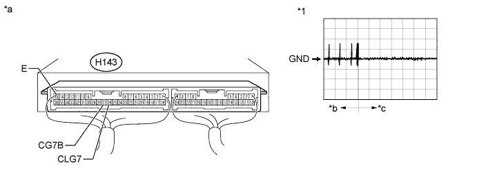
3.CHECK CERTIFICATION ECU (SMART KEY ECU ASSEMBLY) (OUTPUT TO NO. 3 INDOOR ELECTRICAL KEY ANTENNA [INSIDE LUGGAGE])


  1. Connect the H143 certification ECU (smart key ECU assembly) connector.


    B250849E28


    Text in Illustration 
    *1
    Waveform
    -
    -
    *a
    Component with harness connected
    (Certification ECU (smart key ECU assembly))
    *b
    Door open
    *c
    After approximately 30 seconds from when the door is closed
    -
    -

  1. Connect the Q12 No. 3 indoor electrical key antenna assembly (inside luggage) connector.

  1. Using an oscilloscope, check the waveform.

    OK:

    Tester Connection
    Switch Condition
    Tool Setting
    Specified Condition
    H143-26 (CLG7) - H143-15 (E)
    Procedure:
    1. Power switch off
    2. Door is open
    3. Door is closed
    4. 30 seconds elapse
    2 V/DIV., 500 ms/DIV.
    Pulse generation (See waveform)
    H143-27 (CG7B) - H143-15 (E)
    Procedure:
    1. Power switch off
    2. Door is open
    3. Door is closed
    4. 30 seconds elapse
    2 V/DIV., 500 ms/DIV.
    Pulse generation (See waveform)


NG
REPLACE CERTIFICATION ECU (SMART KEY ECU ASSEMBLY)
OK


4.REPLACE NO. 3 INDOOR ELECTRICAL KEY ANTENNA ASSEMBLY (INSIDE LUGGAGE)
  1. Temporarily replace the No. 3 indoor electrical key antenna assembly (inside luggage) with a new or normally functioning one (Click here).


NEXT


5.CLEAR DTC
  1. Clear the DTCs (Click here).


NEXT


6.CHECK FOR DTC
  1. Check for DTCs (Click here).

    OK:
    DTC B27A7 is not output.


NG
REPLACE CERTIFICATION ECU (SMART KEY ECU ASSEMBLY)
OK

END (NO. 3 INDOOR ELECTRICAL KEY ANTENNA ASSEMBLY WAS DEFECTIVE)