DTC    P0A78-202    Drive Motor "A" Inverter Performance

for Preparation Click here


DESCRIPTION

For a description of the inverter (Click here).

DTC No.
INF Code
DTC Detection Condition
Trouble Area
P0A78
202
Malfunction (short circuit) in the motor inverter inside the inverter with converter assembly
  1. Inverter with converter assembly
  2. Hybrid vehicle transaxle assembly
  3. Motor cable

INSPECTION PROCEDURE

CAUTION:
  1. Before inspecting the high-voltage system or disconnecting the low voltage connector of the inverter with converter assembly, take safety precautions such as wearing insulated gloves and removing the service plug grip to prevent electrical shocks. After removing the service plug grip, put it in your pocket to prevent other technicians from accidentally reconnecting it while you are working on the high-voltage system.
  2. After removing the service plug grip, wait for at least 10 minutes before touching any of the high-voltage connectors or terminals. After waiting for 10 minutes, check the voltage at the terminals in the inspection point in the inverter with converter assembly. The voltage should be 0 V before beginning work (Click here).

    HINT:
    Waiting for at least 10 minutes is required to discharge the high-voltage capacitor inside the inverter with converter assembly.

NOTICE:
  1. After turning the power switch off, waiting time may be required before disconnecting the cable from the negative (-) auxiliary battery terminal. Therefore, make sure to read the disconnecting the cable from the negative (-) auxiliary battery terminal notices before proceeding with work (Click here).
  2. DTC P0A78-202 is stored after any of DTCs P0A78-113, 128, 284, 286, 287, 505, 506, 806, 807 and 808 are stored. After troubleshooting and repairing DTC P0A78-202, be sure to troubleshoot all the other DTCs.
  3. Depending on the conditions in which the vehicle is being operated when a short circuit occurs in the inverter with converter assembly, the hybrid vehicle transaxle assembly may be affected. As this DTC is stored if a short circuit occurs in the inverter with converter assembly, it is necessary to perform a road test to check the hybrid vehicle transaxle assembly. If problems are found, replace the malfunctioning parts.
  4. After completing the repair, including the repair of previously output DTCs, drive the vehicle at a speed of approximately 40 km/h (25 mph) for 1 minute and check that DTC P0A90-251 (Drive Motor "A" Performance) is not output. If DTC P0A90-251 (Drive Motor "A" Performance) is output, replace the hybrid vehicle transaxle assembly.

1.CHECK HYBRID VEHICLE TRANSAXLE ASSEMBLY (MG2)

CAUTION:
Be sure to wear insulated gloves.

  1. Check that the service plug grip is not installed.
    NOTICE:
    After removing the service plug grip, do not turn the power switch on (READY), unless instructed by the repair manual because this may cause a malfunction.


    A209686
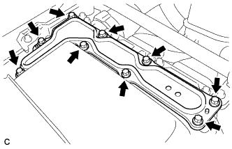
  1. Remove the inverter cover from the inverter with converter assembly.
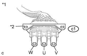
  1. Disconnect the generator cable and motor cable from the inverter with converter assembly.


    A215630E10
  1. Check MG2 for an interphase short using a milliohmmeter.

    1. Using a milliohmmeter, measure the resistance according to the value(s) in the table below.

      HINT:
      If the MG2 temperature is high, the resistance will vary greatly from the specification. Therefore, measure the resistance at least 8 hours after the vehicle is stopped.

      Standard Resistance:
      Tester Connection
      Switch Condition
      Specified Condition
      c1-1 (W) - c1-2 (U)
      Power switch off
      152.6 to 169.0 mΩ
      c1-2 (U) - c1-3 (V)
      Power switch off
      157.6 to 174.0 mΩ
      c1-3 (V) - c1-1 (W)
      Power switch off
      151.6 to 168.0 mΩ

      Text in Illustration 
      *1
      Motor Cable
      *2
      Shield Ground

      HINT:
      To correct the variation of the measured resistance due to temperature, use the following formula to calculate the resistance at 20°C (68°F).
      1. R20 = Rt / {1 + 0.00393 X (T - 20)}
      The calculation is based on the following:
      1. R20: Resistance at 20°C (68°F) (mΩ)
      2. Rt: Measured resistance (mΩ)
      3. T: Temperature when the resistance is measured (°C)

  1. Using a megohmmeter set to 500 V, measure the resistance according to the value(s) in the table below.

    NOTICE:
    Be sure to set the megohmmeter to 500 V when performing this test. Using a setting higher than 500 V can result in damage to the component being inspected.

    Standard Resistance:
    Tester Connection
    Switch Condition
    Specified Condition
    c1-1 (W) - Body ground and shield ground
    Power switch off
    100 MΩ or higher
    c1-2 (U) - Body ground and shield ground
    Power switch off
    100 MΩ or higher
    c1-3 (V) - Body ground and shield ground
    Power switch off
    100 MΩ or higher

  1. Connect the generator cable and motor cable.

  1. Install the inverter cover.


NG
Go to step 4
OK


2.REPLACE INVERTER WITH CONVERTER ASSEMBLY
  1. Replace the inverter with converter assembly (Click here).


NEXT


3.CHECK DTC OUTPUT (HYBRID CONTROL)
  1. Connect the intelligent tester to the DLC3.

  1. Turn the power switch on (IG).

  1. Enter the following menus: Powertrain / Hybrid Control / DTC.

  1. Check the other DTCs that were output together with DTC P0A78-202.

    Result:

    DTC No.
    Relevant Diagnosis
    P0A78-113, 128, 284, 286, 287, 505, 506, 806, 807, 808
    Drive Motor "A" Inverter Performance

    NOTICE:
    DTC P0A78-202 is stored after any of DTCs P0A78-113, 128, 284, 286, 287, 505, 506, 806, 807 and 808 are stored. After troubleshooting and repairing DTC P0A78-202, be sure to troubleshoot all the other DTCs.

  1. Turn the power switch off.


NEXT

GO TO DTC CHART (HYBRID CONTROL SYSTEM) (Click here)  

4.CHECK MOTOR CABLE

CAUTION:
Be sure to wear insulated gloves.

  1. Check that the service plug grip is not installed.

    NOTICE:
    After removing the service plug grip, do not turn the power switch on (READY), unless instructed by the repair manual because this may cause a malfunction.

  1. Remove the motor cable.


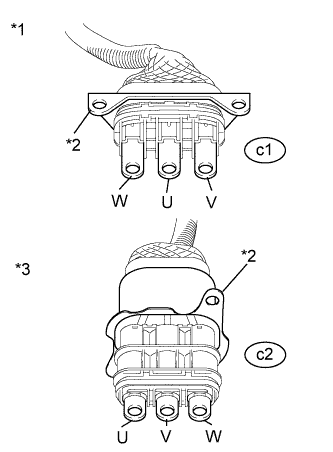
    A217728E06
  1. Using a megohmmeter set to 500 V, measure the resistance according to the value(s) in the table below.

    NOTICE:
    Be sure to set the megohmmeter to 500 V when performing this test. Using a setting higher than 500 V can result in damage to the component being inspected.

    Standard Resistance:
    Tester Connection
    Switch Condition
    Specified Condition
    c1-1 (W) - Body ground and shield ground
    Power switch off
    100 MΩ or higher
    c1-2 (U) - Body ground and shield ground
    Power switch off
    100 MΩ or higher
    c1-3 (V) - Body ground and shield ground
    Power switch off
    100 MΩ or higher

    Text in Illustration 
    *1
    Motor Cable
    (Inverter with Converter Assembly Side)
    *2
    Shielded Ground
    *3
    Motor Cable
    (Hybrid Vehicle Transaxle Assembly Side)

    NOTICE:
    Wrap the terminal of the three-phase AC cable with insulating tape to prevent them from coming into contact with body ground

  1. Measure the resistance according to the value(s) in the table below.

    Standard Resistance:
    Tester Connection
    Switch Condition
    Specified Condition
    c1-1 (W) - c2-1 (W)
    Power switch off
    Below 1 Ω
    c1-2 (U) - c2-3 (U)
    Power switch off
    Below 1 Ω
    c1-3 (V) - c2-2 (V)
    Power switch off
    Below 1 Ω
    c1-1 (W) - c2-3 (U)
    Power switch off
    100 MΩ or higher
    c1-2 (U) - c2-2 (V)
    Power switch off
    100 MΩ or higher
    c1-3 (V) - c2-1 (W)
    Power switch off
    100 MΩ or higher

  1. Install the motor cable.


NG
Go to step 8
OK


5.REPLACE HYBRID VEHICLE TRANSAXLE ASSEMBLY
  1. Replace the hybrid vehicle transaxle assembly (Click here).


NEXT


6.REPLACE INVERTER WITH CONVERTER ASSEMBLY
  1. Replace the inverter with converter assembly (Click here).


NEXT


7.CHECK DTC OUTPUT (HYBRID CONTROL)
  1. Connect the intelligent tester to the DLC3.

  1. Turn the power switch on (IG).

  1. Enter the following menus: Powertrain / Hybrid Control / DTC.

  1. Check the other DTCs that were output together with DTC P0A78-202.

    Result:

    DTC No.
    Relevant Diagnosis
    P0A78-113, 128, 284, 286, 287, 505, 506, 806, 807, 808
    Drive Motor "A" Inverter Performance

    NOTICE:
    DTC P0A78-202 is stored after any of DTCs P0A78-113, 128, 284, 286, 287, 505, 506, 806, 807 and 808 are stored. After troubleshooting and repairing DTC P0A78-202, be sure to troubleshoot all the other DTCs.

  1. Turn the power switch off.


NEXT

GO TO DTC CHART (HYBRID CONTROL SYSTEM) (Click here)  

8.CHECK HYBRID VEHICLE TRANSAXLE ASSEMBLY (MG2)

CAUTION:
Be sure to wear insulated gloves.

  1. Check that the service plug grip is not installed.

    NOTICE:
    After removing the service plug grip, do not turn the power switch on (READY), unless instructed by the repair manual because this may cause a malfunction.

  1. Disconnect the motor cable from the hybrid vehicle transaxle assembly.
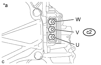


    A217053E06
  1. Check MG2 for an interphase short using a milliohmmeter.

    1. Using a milliohmmeter, measure the resistance according to the value(s) in the table below.

      HINT:
      If the MG2 temperature is high, the resistance will vary greatly from the specification. Therefore, measure the resistance at least 8 hours after the vehicle is stopped.

      Standard Resistance:
      Tester Connection
      Switch Condition
      Specified Condition
      c2-1 (W) - c2-3 (U)
      Power switch off
      149 to 165 mΩ
      c2-2 (V) - c2-1 (W)
      Power switch off
      148 to 164 mΩ
      c2-3 (U) - c2-2 (V)
      Power switch off
      154 to 170 mΩ

      Text in Illustration 
      *a
      Component without motor cable connected
      (Hybrid Vehicle Transaxle Assembly)

      HINT:
      To correct the variation of the measured resistance due to temperature, use the following formula to calculate the resistance at 20°C (68° F).
      1. R20 = Rt / {1 + 0.00393 X (T - 20)}
      The calculation is based on the following:
      1. R20: Resistance at 20°C (68° F) (mΩ)
      2. Rt: Measured resistance (mΩ)
      3. T: Temperature when the resistance is measured (° C)

  1. Using a megohmmeter set to 500 V, measure the resistance according to the value(s) in the table below.

    NOTICE:
    Be sure to set the megohmmeter to 500 V when performing this test. Using a setting higher than 500 V can result in damage to the component being inspected.

    Standard Resistance:
    Tester Connection
    Switch Condition
    Specified Condition
    c2-1 (W) - Body ground and shield ground
    Power switch off
    100 MΩ or higher
    c2-2 (V) - Body ground and shield ground
    Power switch off
    100 MΩ or higher
    c2-3 (U) - Body ground and shield ground
    Power switch off
    100 MΩ or higher

  1. Connect the motor cable.


NG
Go to step 12
OK


9.REPLACE MOTOR CABLE
  1. Replace the motor cable (Click here).


NEXT


10.REPLACE INVERTER WITH CONVERTER ASSEMBLY
  1. Replace the inverter with converter assembly (Click here).


NEXT


11.CHECK DTC OUTPUT (HYBRID CONTROL)
  1. Connect the intelligent tester to the DLC3.

  1. Turn the power switch on (IG).

  1. Enter the following menus: Powertrain / Hybrid Control / DTC.

  1. Check the other DTCs that were output together with DTC P0A78-202.

    Result:

    DTC No.
    Relevant Diagnosis
    P0A78-113, 128, 284, 286, 287, 505, 506, 806, 807, 808
    Drive Motor "A" Inverter Performance

    NOTICE:
    DTC P0A78-202 is stored after any of DTCs P0A78-113, 128, 284, 286, 287, 505, 506, 806, 807 and 808 are stored. After troubleshooting and repairing DTC P0A78-202, be sure to troubleshoot all the other DTCs.

  1. Turn the power switch off.


NEXT

GO TO DTC CHART (HYBRID CONTROL SYSTEM) (Click here)  

12.REPLACE MOTOR CABLE
  1. Replace the motor cable (Click here).


NEXT


13.REPLACE HYBRID VEHICLE TRANSAXLE ASSEMBLY
  1. Replace the hybrid vehicle transaxle assembly (Click here).


NEXT


14.REPLACE INVERTER WITH CONVERTER ASSEMBLY
  1. Replace the inverter with converter assembly (Click here).


NEXT


15.CHECK DTC OUTPUT (HYBRID CONTROL)
  1. Connect the intelligent tester to the DLC3.

  1. Turn the power switch on (IG).

  1. Enter the following menus: Powertrain / Hybrid Control / DTC.

  1. Check the other DTCs that were output together with DTC P0A78-202.

    Result:

    DTC No.
    Relevant Diagnosis
    P0A78-113, 128, 284, 286, 287, 505, 506, 806, 807, 808
    Drive Motor "A" Inverter Performance

    NOTICE:
    DTC P0A78-202 is stored after any of DTCs P0A78-113, 128, 284, 286, 287, 505, 506, 806, 807 and 808 are stored. After troubleshooting and repairing DTC P0A78-202, be sure to troubleshoot all the other DTCs.

  1. Turn the power switch off.


NEXT

GO TO DTC CHART (HYBRID CONTROL SYSTEM) (Click here)