DTC B2658 Short in Sensor with Motor Power Supply Circuit |
| DTC Code | DTC Detection Condition | Trouble Area |
| B2658 | A problem with the voltage supplied to the position control sensor. |
|
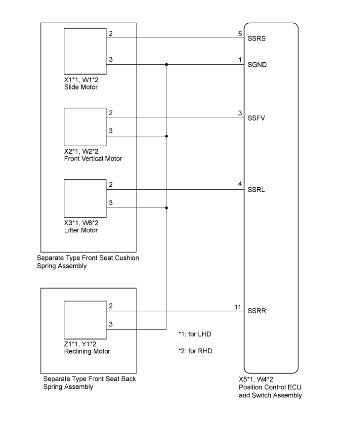
| 1.CHECK FOR DTC |
Clear the DTCs (Click here).
Check for DTCs (Click here).
|
| ||||
| OK | ||
 | ||
| ||
| 2.CHECK HARNESS AND CONNECTOR (POSITION CONTROL ECU AND SWITCH ASSEMBLY - SLIDE MOTOR) |
Disconnect the X5*1 or W4*2 position control ECU and switch assembly connector.
Disconnect the X1*1 or W1*2 slide motor connector.
Measure the resistance according to the value(s) in the table below.
| Tester Connection | Condition | Specified Condition |
| X5-5 (SSRS) - X1-2 | Always | Below 1 Ω |
| X5-1 (SGND) - X1-3 | Always | Below 1 Ω |
| X5-5 (SSRS) - X5-1 (SGND) | Always | 10 kΩ or higher |
| X5-5 (SSRS) - Body ground | Always | 10 kΩ or higher |
| X5-1 (SGND) - Body ground | Always | 10 kΩ or higher |
| Tester Connection | Condition | Specified Condition |
| W4-5 (SSRS) - W1-2 | Always | Below 1 Ω |
| W4-1 (SGND) - W1-3 | Always | Below 1 Ω |
| W4-5 (SSRS) - W4-1 (SGND) | Always | 10 kΩ or higher |
| W4-5 (SSRS) - Body ground | Always | 10 kΩ or higher |
| W4-1 (SGND) - Body ground | Always | 10 kΩ or higher |
|
| ||||
| OK | |
 |
| 3.CHECK POSITION CONTROL ECU AND SWITCH ASSEMBLY (SLIDE MOTOR CIRCUIT) |
Measure the voltage according to the value(s) in the table below.
| Tester Connection | Switch Condition | Specified Condition |
| X1-2 - X1-3 | Sliding switch on | 4.8 to 5.1 V |
| Tester Connection | Switch Condition | Specified Condition |
| W1-2 - W1-3 | Sliding switch on | 4.8 to 5.1 V |
|
| ||||
| OK | |
|
| 4.CHECK HARNESS AND CONNECTOR (POSITION CONTROL ECU AND SWITCH - FRONT VERTICAL MOTOR) |
Disconnect the X2*1 or W2*2 front vertical motor connector.
Measure the resistance according to the value(s) in the table below.
| Tester Connection | Condition | Specified Condition |
| X5-3 (SSFV) - X2-2 | Always | Below 1 Ω |
| X5-1 (SGND) - X2-3 | Always | Below 1 Ω |
| X5-3 (SSFV) - X5-1 (SGND) | Always | 10 kΩ or higher |
| X5-3 (SSFV) - Body ground | Always | 10 kΩ or higher |
| X5-1 (SGND) - Body ground | Always | 10 kΩ or higher |
| Tester Connection | Condition | Specified Condition |
| W4-3 (SSFV) - W2-2 | Always | Below 1 Ω |
| W4-1 (SGND) - W2-3 | Always | Below 1 Ω |
| W4-3 (SSFV) - W4-1 (SGND) | Always | 10 kΩ or higher |
| W4-3 (SSFV) - Body ground | Always | 10 kΩ or higher |
| W4-1 (SGND) - Body ground | Always | 10 kΩ or higher |
|
| ||||
| OK | |
|
| 5.CHECK POSITION CONTROL ECU AND SWITCH ASSEMBLY (FRONT VERTICAL MOTOR CIRCUIT) |
Measure the voltage according to the value(s) in the table below.
| Tester Connection | Switch Condition | Specified Condition |
| X2-2 - X2-3 | Front vertical switch on | 4.8 to 5.1 V |
| Tester Connection | Switch Condition | Specified Condition |
| W2-2 - W2-3 | Front vertical switch on | 4.8 to 5.1 V |
|
| ||||
| OK | |
|
| 6.CHECK HARNESS AND CONNECTOR (POSITION CONTROL ECU AND SWITCH ASSEMBLY - LIFTER MOTOR) |
Disconnect the X3*1 or W6*2 lifter motor connector.
Measure the resistance according to the value(s) in the table below.
| Tester Connection | Condition | Specified Condition |
| X5-4 (SSRL) - X3-2 | Always | Below 1 Ω |
| X5-1 (SGND) - X3-3 | Always | Below 1 Ω |
| X5-4 (SSRL) - X5-1 (SGND) | Always | 10 kΩ or higher |
| X5-4 (SSRL) - Body ground | Always | 10 kΩ or higher |
| X5-1 (SGND) - Body ground | Always | 10 kΩ or higher |
| Tester Connection | Condition | Specified Condition |
| W4-4 (SSRL) - W6-2 | Always | Below 1 Ω |
| W4-1 (SGND) - W6-3 | Always | Below 1 Ω |
| W4-4 (SSRL) - W4-1 (SGND) | Always | 10 kΩ or higher |
| W4-4 (SSRL) - Body ground | Always | 10 kΩ or higher |
| W4-1 (SGND) - Body ground | Always | 10 kΩ or higher |
|
| ||||
| OK | |
|
| 7.CHECK POSITION CONTROL ECU AND SWITCH ASSEMBLY (LIFTER MOTOR CIRCUIT) |
Measure the voltage according to the value(s) in the table below.
| Tester Connection | Switch Condition | Specified Condition |
| X3-2 - X3-3 | Lifter switch on | 4.8 to 5.1 V |
| Tester Connection | Switch Condition | Specified Condition |
| W6-2 - W6-3 | Lifter switch on | 4.8 to 5.1 V |
|
| ||||
| OK | |
|
| 8.REPLACE SEPARATE TYPE FRONT SEAT CUSHION SPRING ASSEMBLY |
Replace the separate type front seat cushion spring assembly (Click here).
Clear the DTCs (Click here).
Check for DTCs (Click here).
|
| ||||
| OK | ||
| ||
| ||
| 9.CHECK HARNESS AND CONNECTOR (POSITION CONTROL ECU AND SWITCH ASSEMBLY - RECLINING MOTOR) |
Disconnect the X5*1 or W4*2 position control ECU and switch assembly connector.
Disconnect the Z1*1 or Y1*2 reclining motor connector.
Measure the resistance according to the value(s) in the table below.
| Tester Connection | Condition | Specified Condition |
| X5-11 (SSRR) - Z1-2 | Always | Below 1 Ω |
| X5-1 (SGND) - Z1-3 | Always | Below 1 Ω |
| X5-11 (SSRR) - X5-1 (SGND) | Always | 10 kΩ or higher |
| X5-11 (SSRR) - Body ground | Always | 10 kΩ or higher |
| X5-1 (SGND) - Body ground | Always | 10 kΩ or higher |
| Tester Connection | Condition | Specified Condition |
| W4-11 (SSRR) - Y1-2 | Always | Below 1 Ω |
| W4-1 (SGND) - Y1-3 | Always | Below 1 Ω |
| W4-11 (SSRR) - W4-1 (SGND) | Always | 10 kΩ or higher |
| W4-11 (SSRR) - Body ground | Always | 10 kΩ or higher |
| W4-1 (SGND) - Body ground | Always | 10 kΩ or higher |
|
| ||||
| OK | |
|
| 10.CHECK POSITION CONTROL ECU AND SWITCH ASSEMBLY (RECLINING MOTOR CIRCUIT) |
Measure the voltage according to the value(s) in the table below.
| Tester Connection | Switch Condition | Specified Condition |
| Z1-2 - Z1-3 | Reclining switch on | 4.8 to 5.1 V |
| Tester Connection | Switch Condition | Specified Condition |
| Y1-2 - Y1-3 | Reclining switch on | 4.8 to 5.1 V |
|
| ||||
| OK | |
|
| 11.REPLACE SEPARATE TYPE FRONT SEAT BACK SPRING ASSEMBLY |
Replace the separate type front seat back spring assembly (Click here).
Clear the DTCs (Click here).
Check for DTCs (Click here).
|
| ||||
| OK | ||
| ||
| ||


