MAIN BODY ECU > INSTALLATION |
| 1. INSTALL MAIN BODY ECU (for LHD) |
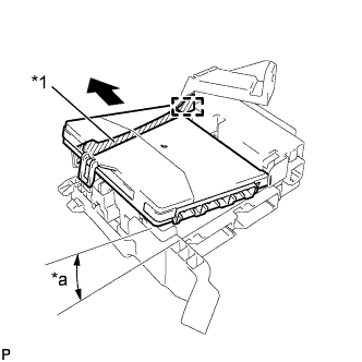 |
Insert the main body ECU up to the position it contacts the housing sidewall of the guide as shown in the illustration.
| *1 | Housing Sidewall |
| *a | 20° |
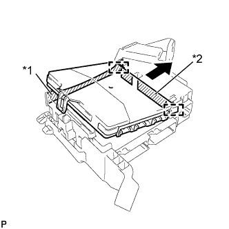 |
Slide the guide of the main body ECU along the housing sidewall so that it contacts the junction block fuses as shown in the illustration.
| *1 | Housing Sidewall |
| *2 | Junction Block Fuse |
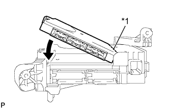 |
While contacting the main body ECU to side A of the junction block (axis of rotation), rotate it downward as shown in the illustration.
| *1 | Side A Contact Portion |
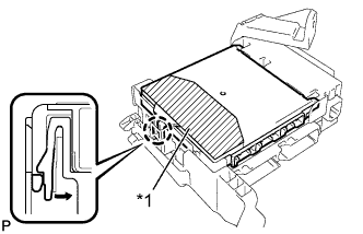 |
Press the push area until the claw engages to install the main body ECU.
| *1 | Push Area |
| 2. INSTALL MAIN BODY ECU (for RHD) |
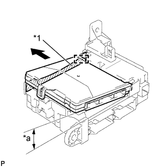 |
Insert the main body ECU up to the position it contacts the housing sidewall of the guide as shown in the illustration.
| *1 | Housing Sidewall |
| *a | 20° |
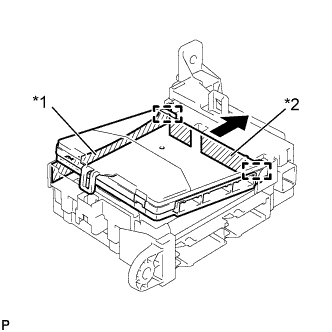 |
Slide the guide of the main body ECU along the housing sidewall so that it contacts the junction block fuses as shown in the illustration.
| *1 | Housing Sidewall |
| *2 | Junction Block Fuse |
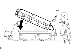 |
While contacting the main body ECU to side A of the junction block (point of rotation), rotate it downward as shown in the illustration.
| *1 | Side A Contact Portion |
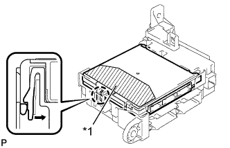 |
Press the push area until the claw engages to install the main body ECU.
| *1 | Push Area |
| 3. INSTALL INSTRUMENT PANEL JUNCTION BLOCK ASSEMBLY (for LHD) |
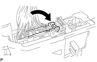 |
Engage the claw to install the connector as shown in the illustration.
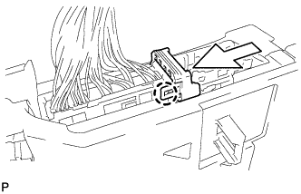 |
Engage the claw to lock the connector lock as shown in the illustration.
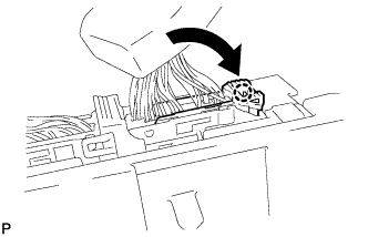 |
Engage the claw to connect the connector as shown in the illustration.
Engage the 2 clamps to connect the wire harness.
Install the instrument panel junction block assembly with the bolt and nut.
Connect each connector.
| 4. INSTALL INSTRUMENT PANEL JUNCTION BLOCK ASSEMBLY (for RHD) |
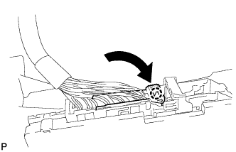 |
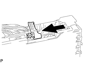
Engage the claw to install the connector as shown in the illustration.
 |
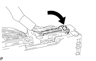
Engage the claw to lock the connector lock as shown in the illustration.
 |
Engage the claw to connect the connector as shown in the illustration.
Install the instrument panel junction block assembly with the bolt and nut.
Connect each connector.
| 5. INSTALL ECU INTEGRATION BOX LH (for RHD) |
Install the ECU integration box LH with the nut and bolt.
Engage the clamp to connect the wire harness.
Connect each connector.
| 6. INSTALL LOWER INSTRUMENT PANEL SUB-ASSEMBLY |
