MAIN BODY ECU > REMOVAL |
| 1. REMOVE LOWER INSTRUMENT PANEL SUB-ASSEMBLY |
| 2. REMOVE INSTRUMENT PANEL JUNCTION BLOCK ASSEMBLY (for LHD) |
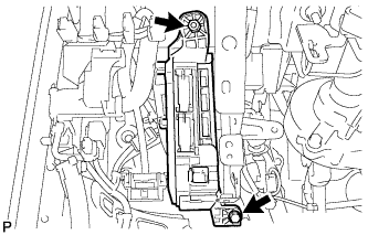 |
Disconnect each connector.
Remove the bolt and nut, and disconnect the instrument panel junction block assembly.
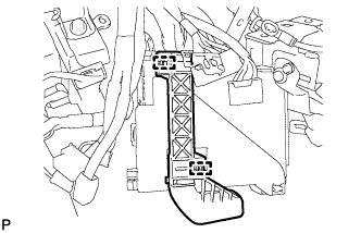 |
Disengage the 2 clamps and disconnect the wire harness.
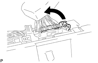 |
Disengage the claw and disconnect the connector as shown in the illustration.
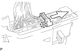 |
Disengage the claw and release the connector lock as shown in the illustration.
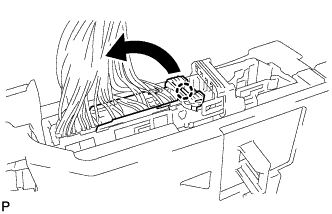 |
Disengage the claw and disconnect the connector as shown in the illustration.
Remove the instrument panel junction block assembly.
| 3. REMOVE ECU INTEGRATION BOX LH (for RHD) |
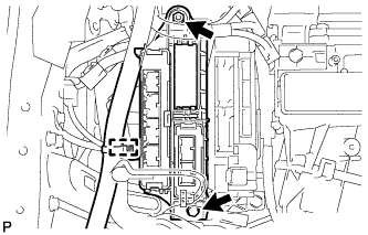 |
Disconnect each connector.
Disengage the clamp and disconnect the wire harness.
Remove the bolt, nut and ECU integration box LH.
| 4. REMOVE INSTRUMENT PANEL JUNCTION BLOCK ASSEMBLY (for RHD) |
Disconnect each connector.
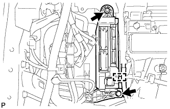 |
Disengage the clamp.
Remove the bolt and nut, and disconnect the instrument panel junction block assembly.
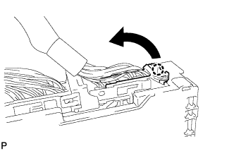 |
Disengage the claw and disconnect the connector as shown in the illustration.
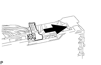 |
Disengage the claw and release the connector lock as shown in the illustration.
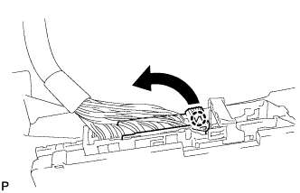 |
Disengage the claw and disconnect the connector as shown in the illustration.
Remove the instrument panel junction block assembly.
| 5. REMOVE MAIN BODY ECU (for LHD) |
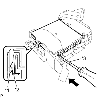 |
Press the claw of the junction block as shown in the illustration to release the lock.
| *1 | Main Body ECU |
| *2 | Claw of Driver Side Junction Block |
| *3 | Protective Tape |
With the junction block lock released, insert a screwdriver with its tip wrapped with protective tape horizontally between the main body ECU and junction block.
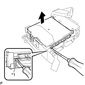 |
Using the screwdriver, carefully raise the main body ECU up to the position where the connector becomes disengaged.
| *1 | Protective Tape |
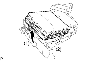 |
Raise the main body ECU as shown by the arrow (1), and then pull it out as shown by the arrow (2) in the illustration.
| 6. REMOVE MAIN BODY ECU (for RHD) |
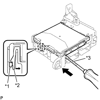 |
Press the claw of the junction block as shown in the illustration to release the lock.
| *1 | Main Body ECU |
| *2 | Claw of Driver Side Junction Block |
| *3 | Protective Tape |
With the junction block lock released, insert a screwdriver with its tip wrapped with protective tape horizontally between the main body ECU and junction block.
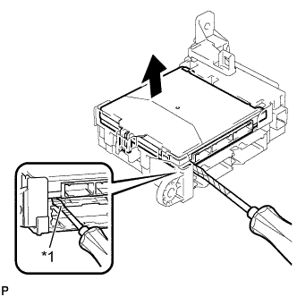 |
Using the screwdriver, carefully raise the main body ECU up to the position where the connector becomes disengaged.
| *1 | Protective Tape |
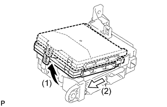 |
Raise the main body ECU as shown by the arrow (1), and then pull it out as shown by the arrow (2) shown in the illustration.
