POWER MANAGEMENT CONTROL ECU > REMOVAL |
| 1. PRECAUTION |
| 2. REMOVE REAR NO. 2 FLOOR BOARD |
Remove the rear No. 2 floor board.
| 3. REMOVE REAR DECK FLOOR BOX |
Remove the rear deck floor box.
| 4. REMOVE REAR NO. 3 FLOOR BOARD |
Remove the rear No. 3 floor board.
| 5. REMOVE DECK FLOOR BOX RH |
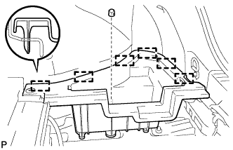 |
Remove the clip.
Disengage the 6 guides and remove the deck floor box RH.
| 6. REMOVE REAR FLOOR BOARD UPPER NO. 3 PLATE |
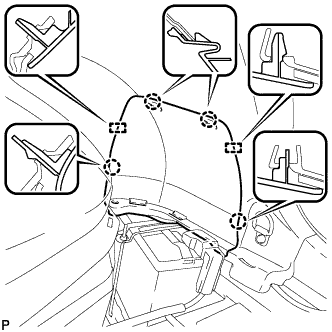 |
Disengage the 4 claws and 2 guides, and remove the rear floor board upper No. 3 plate.
| 7. DISCONNECT CABLE FROM NEGATIVE BATTERY TERMINAL |
| 8. DISCONNECT FRONT DOOR OPENING TRIM WEATHERSTRIP RH (for LHD) |
| 9. REMOVE FRONT DOOR SCUFF PLATE RH (for LHD) |
| 10. REMOVE COWL SIDE TRIM SUB-ASSEMBLY RH (for LHD) |
| 11. REMOVE INSTRUMENT SIDE PANEL RH (for LHD) |
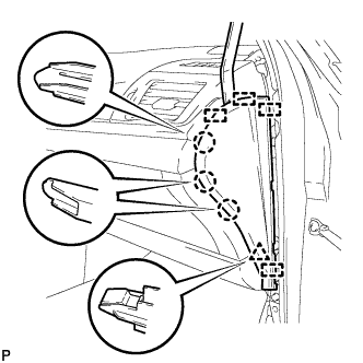 |
Using a moulding remover, disengage the 3 claws, clip and 4 guides, and remove the instrument side panel RH.
Disconnect the connector.
| 12. REMOVE NO. 2 INSTRUMENT PANEL UNDER COVER SUB-ASSEMBLY (for LHD) |
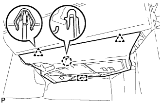 |
Disengage the 2 clips, claw and guide.
Disengage the clamp.
Disconnect the connector and remove the No. 2 instrument panel under cover sub-assembly.
| 13. REMOVE LOWER NO. 2 INSTRUMENT PANEL AIRBAG ASSEMBLY (for LHD) |
Check that the power switch is off.
Check that the cable is disconnected from the negative (-) auxiliary battery terminal.
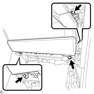 |
Remove the 3 bolts.
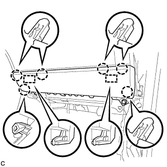 |
Disengage the 6 claws and 2 guides to separate the lower No. 2 instrument panel airbag assembly.
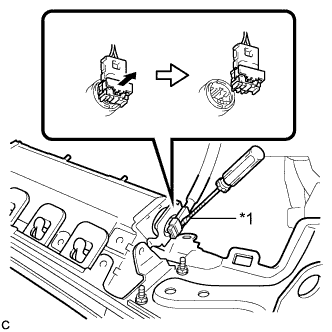 |
Using a screwdriver with the tip wrapped with protective tape, release the airbag connector lock.
| *1 | Protective Tape |
Disconnect the airbag connector to remove the lower No. 2 instrument panel airbag assembly.
| 14. REMOVE GLOVE COMPARTMENT DOOR ASSEMBLY (for LHD) |
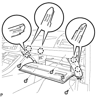 |
Remove the 4 screws <C>.
Disengage the 5 claws.
Disengage the clamp.
Disconnect the connector and remove the glove compartment door assembly.
| 15. REMOVE ECU INTEGRATION BOX RH (for LHD) |
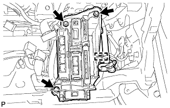 |
Disconnect each connector.
Disengage the clamp and disconnect the wire harness.
Remove the bolt, 2 nuts and ECU integration box RH.
| 16. REMOVE POWER MANAGEMENT CONTROL ECU (for LHD) |
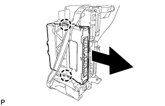 |
Disengage the 2 claws and remove the power management control ECU as shown in the illustration.
| 17. DISCONNECT FRONT DOOR OPENING TRIM WEATHERSTRIP LH (for RHD) |
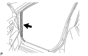 |
Disconnect the front door opening trim weatherstrip.
Remove the residual weatherstrip sealant from the body of the vehicle using cleaner.
| 18. REMOVE FRONT DOOR SCUFF PLATE LH (for RHD) |
 |
Disengage the 4 claws, 2 guides and 4 clips, and remove the front door scuff plate LH.
| 19. REMOVE COWL SIDE TRIM SUB-ASSEMBLY LH (for RHD) |
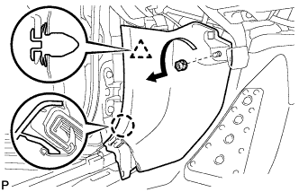 |
Remove the clip as shown in the illustration.
Disengage the clip and claw, and remove the cowl side trim sub-assembly LH.
| 20. REMOVE INSTRUMENT SIDE PANEL LH (for RHD) |
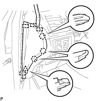 |
Using a moulding remover, disengage the 3 claws, clip and 4 guides, and remove the instrument side panel LH.
| 21. REMOVE NO. 2 INSTRUMENT PANEL UNDER COVER SUB-ASSEMBLY (for RHD) |
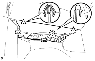 |
Disengage the 2 clips, claw and 2 guides.
Disengage the clamp.
Disconnect the connector and remove the No. 2 instrument panel under cover sub-assembly.
| 22. REMOVE LOWER NO. 2 INSTRUMENT PANEL AIRBAG ASSEMBLY (for RHD) |
Check that the power switch is off.
Check that the cable is disconnected from the negative (-) auxiliary battery terminal.
|
Remove the 3 bolts.
|
Disengage the 6 claws and 2 guides to separate the lower No. 2 instrument panel airbag assembly.
|
Using a screwdriver with the tip wrapped with protective tape, release the airbag connector lock.
| *1 | Protective Tape |
Disconnect the airbag connector to remove the lower No. 2 instrument panel airbag assembly.
| 23. REMOVE GLOVE COMPARTMENT DOOR ASSEMBLY (for RHD) |
|
Remove the 4 screws <C>.
Disengage the 5 claws.
Disengage the clamp.
Disconnect the connector and remove the glove compartment door assembly.
| 24. REMOVE ECU INTEGRATION BOX LH (for RHD) |
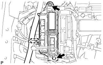 |
Disconnect each connector.
Disengage the clamp and disconnect the wire harness.
Remove the bolt, nut and ECU integration box LH.
| 25. REMOVE POWER MANAGEMENT CONTROL ECU (for RHD) |
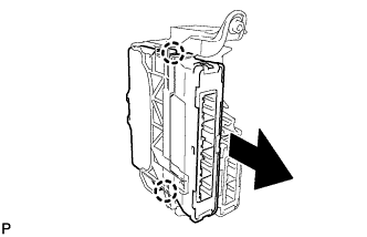 |
Disengage the 2 claws and remove the power management control ECU as shown in the illustration.
