AUDIO AND VISUAL SYSTEM (w/o Navigation System) > Dimmer Signal Circuit |
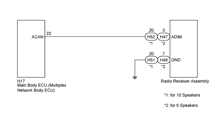
| 1.INSPECT MAIN BODY ECU (MULTIPLEX NETWORK BODY ECU) |
Disconnect the radio receiver assembly connector.
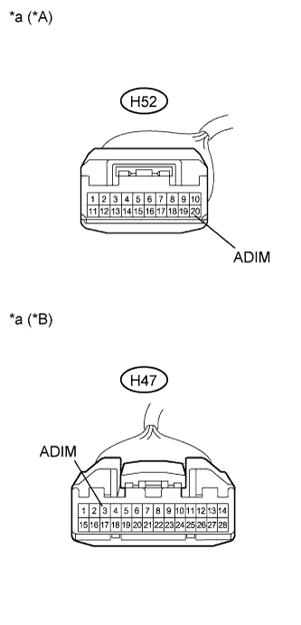 |
Measure the voltage according to the value(s) in the table below.
| Tester Connection | Condition | Specified Condition |
| H52-20 (ADIM) - Body ground | Power switch on (IG), automatic light control sensor covered by hand, and light control switch in the tail or head position | 11 to 14 V |
| Tester Connection | Condition | Specified Condition |
| H47-3 (ADIM) - Body ground | Power switch on (IG), automatic light control sensor covered by hand, and light control switch in the tail or head position | 11 to 14 V |
| *A | for 10 Speakers |
| *B | for 6 Speakers |
| *a | Front view of wire harness connector (to Radio Receiver Assembly) |
|
| ||||
| OK | |
 |
| 2.INSPECT RADIO RECEIVER ASSEMBLY |
Disconnect the radio receiver assembly connector.
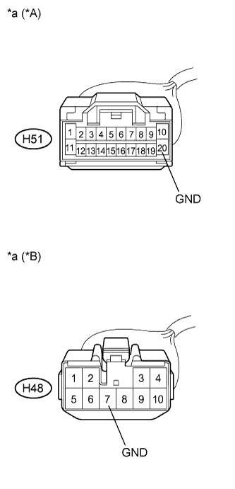 |
Measure the resistance according to the value(s) in the table below
| Tester Connection | Condition | Specified Condition |
| H51-20 (GND) - Body ground | Always | Below 1 Ω |
| Tester Connection | Condition | Specified Condition |
| H48-7 (GND) - Body ground | Always | Below 1 Ω |
| *A | for 10 Speakers |
| *B | for 6 Speakers |
| *a | Front view of wire harness connector (to Radio Receiver Assembly) |
|
| ||||
| OK | ||
 | ||
| ||
| 3.CHECK HARNESS AND CONNECTOR |
Disconnect the radio receiver assembly and main body ECU (multiplex network body ECU) connectors.
Measure the resistance according to the value(s) in the table below.
| Tester Connection | Condition | Specified Condition |
| H17-22 (ACAN) - H52-20 (ADIM) | Always | Below 1 Ω |
| H52-20 (ADIM) - Body ground | Always | 10 kΩ or higher |
| Tester Connection | Condition | Specified Condition |
| H17-22 (ACAN) - H47-3 (ADIM) | Always | Below 1 Ω |
| H47-3 (ADIM) - Body ground | Always | 10 kΩ or higher |
|
| ||||
| OK | ||
| ||
| ||


