DTC B15BB Multi-media Interface ECU Malfunction |
| DTC No. | DTC Detection Condition | Trouble Area |
| B15BB | When one of the conditions below is met:
|
|
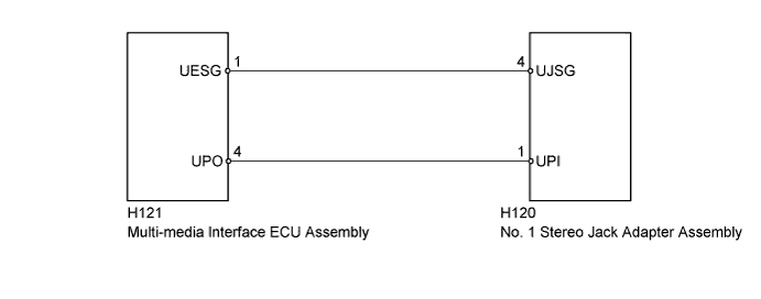
| 1.REPLACE "iPod" OR USB DEVICE |
Disconnect the USB device or "iPod" from the No. 1 stereo jack adapter assembly.
Turn the power switch off.
Turn the power switch on (ACC).
Connect a known good USB device or "iPod" to the No. 1 stereo jack adapter assembly.
| NEXT | |
 |
| 2.CLEAR DTC |
Clear the DTCs (Click here).
| NEXT | |
|
| 3.RECHECK FOR DTC |
Recheck for DTCs and check if the same DTC is output again.
|
| ||||
| OK | ||
 | ||
| ||
| 4.INSPECT MULTI-MEDIA INTERFACE ECU ASSEMBLY |
Disconnect the No. 1 stereo jack adapter assembly connector.
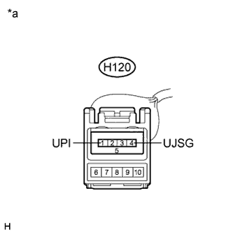 |
Measure the voltage according to the value(s) in the table below.
| Tester Connection | Condition | Specified Condition |
| H120-1 (UPI) - H120-4 (UJSG) | Power switch on (ACC) | 5 V |
| *a | Front view of wire harness connector (to No. 1 Stereo Jack Adapter Assembly) |
|
| ||||
| OK | ||
| ||
| ||
| 5.CHECK HARNESS AND CONNECTOR |
Disconnect the multi-media interface ECU assembly connector.
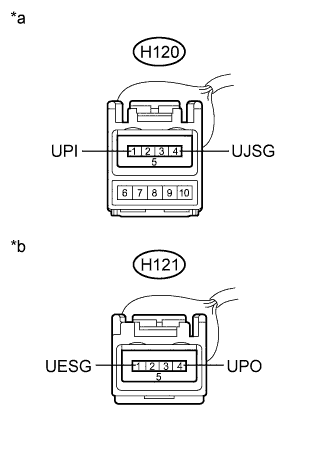 |
Measure the resistance according to the value(s) in the table below.
| Tester Connection | Condition | Specified Condition |
| H121-4 (UPO) - H120-1 (UPI) | Always | Below 1 Ω |
| H121-1 (UESG) - H120-4 (UJSG) | Always | Below 1 Ω |
| H120-1 (UPI) - Body ground | Always | 10 kΩ or higher |
| H120-4 (UJSG) - Body ground | Always | 10 kΩ or higher |
| *a | Front view of wire harness connector (to No. 1 Stereo Jack Adapter Assembly) |
| *b | Front view of wire harness connector (to Multi-media Interface ECU Assembly) |
|
| ||||
| OK | ||
| ||
| ||


