SEAT BELT CONTROL ECU > INSTALLATION |
| 1. INSTALL SEAT BELT CONTROL ECU (for LHD) |
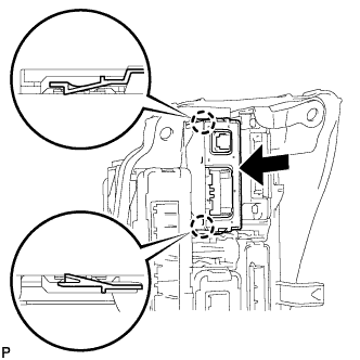 |
Engage the 2 claws to install the seat belt control ECU.
| 2. INSTALL SEAT BELT CONTROL ECU (for RHD) |
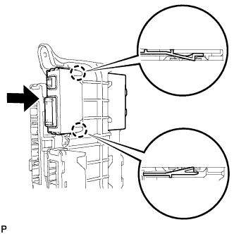 |
Engage the 2 claws to install the seat belt control ECU.
| 3. INSTALL ECU INTEGRATION BOX RH (for LHD) |
Install the ECU integration box RH with the 2 nuts and bolt.
Engage the clamp to connect the wire harness.
Connect each connector.
| 4. INSTALL ECU INTEGRATION BOX LH (for RHD) |
Install the ECU integration box LH with the nut and bolt.
Engage the clamp to connect the wire harness.
Connect each connector.
| 5. INSTALL GLOVE COMPARTMENT DOOR ASSEMBLY |
Connect the connector.
Engage the clamp.
Engage the 5 claws.
Install the glove compartment door assembly with the 4 screws <C>.
| 6. INSTALL LOWER NO. 2 INSTRUMENT PANEL AIRBAG ASSEMBLY |
Check that the power switch is off.
Check that the cable is disconnected from the negative (-) auxiliary battery terminal.
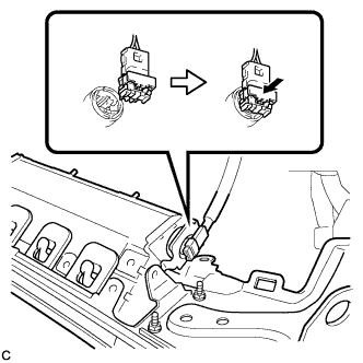 |
Connect the airbag connector to the lower No. 2 instrument panel airbag assembly.
Push in the lock to install the airbag connector.
Temporarily install the lower No. 2 instrument panel airbag assembly with the 6 claws and 2 guides.
Install the 3 bolts.
| 7. INSTALL INSTRUMENT SIDE PANEL |
Connect the connector.
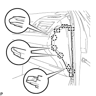 |
Engage the 4 guides, clip and 3 claws to install the instrument side panel RH.
| 8. INSTALL FRONT DOOR OPENING TRIM WEATHERSTRIP |
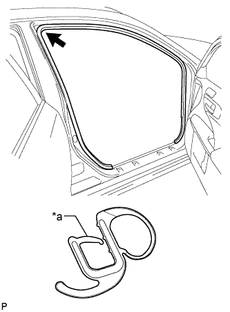 |
Align the alignment mark (light blue) on the weatherstrip with the protruding portion on the body indicated by the arrow in the illustration, and install the front door opening trim weatherstrip RH.
| *a | Alignment Mark (Light blue) |
| 9. INSTALL COWL SIDE TRIM SUB-ASSEMBLY |
| 10. INSTALL FRONT DOOR SCUFF PLATE |
| 11. INSTALL NO. 2 INSTRUMENT PANEL UNDER COVER SUB-ASSEMBLY (for LHD) |
Connect the connector.
Engage the clamp.
Engage the guide, claw and 2 clips to install the No. 2 instrument panel under cover sub-assembly.
| 12. INSTALL NO. 2 INSTRUMENT PANEL UNDER COVER SUB-ASSEMBLY (for RHD) |
Connect the connector.
Engage the clamp.
Engage the 2 guides, claw and 2 clips to install the No. 2 instrument panel under cover sub-assembly.
| 13. CONNECT CABLE TO NEGATIVE BATTERY TERMINAL |
| 14. INSTALL REAR FLOOR BOARD UPPER NO. 3 PLATE |
Engage the 4 claws and 2 guides to install the rear floor board upper No. 3 plate.
| 15. INSTALL DECK FLOOR BOX RH |
Engage the 6 guides.
Install the deck floor box RH with the clip.
| 16. INSTALL REAR NO. 3 FLOOR BOARD |
Install the rear No. 3 floor board.
| 17. INSTALL REAR DECK FLOOR BOX |
Install the rear deck floor box.
| 18. INSTALL REAR NO. 2 FLOOR BOARD |
Install the rear No. 2 floor board.
| 19. INSPECT SRS WARNING LIGHT |
