POWER MIRROR CONTROL SYSTEM (w/ Memory) > Wireless-linked Return Function does not Operate |
| 1.CHECK AUTOMATIC MEMORY CALL FUNCTION (MEMORY REGISTRATION) |
Connect the intelligent tester to the DLC3.
Turn the power switch on (IG).
Turn the intelligent tester on.
Enter the following menus: Body / Main Body / Data List.
After performing any of the following procedures to link the key and a switch, check the Data List to confirm that the key and switch have been linked.
With the power switch off and the driver side door closed, press and hold the M1, M2 or M3 switch. The main body ECU (multiplex network body ECU) will enter transmitter key recognition code registration mode to allow a key to be linked to mirror surface memory position.
When the manual door lock switch is pressed, check that the buzzer of the position control ECU and switch sounds once (0.5 seconds).
| Tester Display | Measurement Item/Range | Normal Condition | Diagnostic Note |
| Mem SW No. w/KeyID1 | Switch linked with key ID1 / NONE, MEM SW1, MEM SW2 or MEM SW3 | NONE: No switches linked with key ID1 MEM SW1: M1 linked with key ID1 MEM SW2: M2 linked with key ID1 MEM SW3: M3 linked with key ID1 | - |
| Mem SW No. w/KeyID2 | Switch linked with key ID2 / NONE, MEM SW1, MEM SW2 or MEM SW3 | NONE: No switches linked with key ID2 MEM SW1: M1 linked with key ID2 MEM SW2: M2 linked with key ID2 MEM SW3: M3 linked with key ID2 | - |
| Mem SW No. w/KeyID3 | Switch linked with key ID3 / NONE, MEM SW1, MEM SW2 or MEM SW3 | NONE: No switches linked with key ID3 MEM SW1: M1 linked with key ID3 MEM SW2: M2 linked with key ID3 MEM SW3: M3 linked with key ID3 | - |
| Mem SW No. w/KeyID4 | Switch linked with key ID4 / NONE, MEM SW1, MEM SW2 or MEM SW3 | NONE: No switches linked with key ID4 MEM SW1: M1 linked with key ID4 MEM SW2: M2 linked with key ID4 MEM SW3: M3 linked with key ID4 | - |
| Mem SW No. w/KeyID5 | Switch linked with key ID5 / NONE, MEM SW1, MEM SW2 or MEM SW3 | NONE: No switches linked with key ID5 MEM SW1: M1 linked with key ID5 MEM SW2: M2 linked with key ID5 MEM SW3: M3 linked with key ID5 | - |
| Mem SW No. w/KeyID6 | Switch linked with key ID6 / NONE, MEM SW1, MEM SW2 or MEM SW3 | NONE: No switches linked with key ID6 MEM SW1: M1 linked with key ID6 MEM SW2: M2 linked with key ID6 MEM SW3: M3 linked with key ID6 | - |
| Mem SW No. w/KeyID7 | Switch linked with key ID7 / NONE, MEM SW1, MEM SW2 or MEM SW3 | NONE: No switches linked with key ID7 MEM SW1: M1 linked with key ID7 MEM SW2: M2 linked with key ID7 MEM SW3: M3 linked with key ID7 | - |
|
| ||||
| OK | |
 |
| 2.CHECK AUTOMATIC MEMORY CALL FUNCTION |
Perform a wireless door unlock operation and check that opening the driver side door causes the following:
| Result | Proceed to |
| The automatic memory call function does not operate together with wireless door unlock operation only. | A |
| The automatic memory call function does not operate together with entry unlock operation only. | B |
| The automatic memory call function does not operate at all. | C |
|
| ||||
|
| ||||
| A | |
|
| 3.CHECK WIRELESS DOOR LOCK CONTROL FUNCTIONS |
Check wireless door lock control operation (Click here).
|
| ||||
| OK | |
|
| 4.CHECK MEMORY AND SEAT RESTORING OPERATION (POWER SEAT CONTROL SYSTEM) |
Check memory and seat restoring operation (Click here).
|
| ||||
| OK | |
|
| 5.REPLACE OUTER MIRROR CONTROL ECU ASSEMBLY |
Replace the outer mirror control ECU assembly (Click here).
| NEXT | |
|
| 6.CHECK AUTOMATIC MEMORY CALL FUNCTION |
Perform registration for automatic memory call function (Click here).
Perform a wireless door unlock operation and check that opening the driver side door causes the following:
|
| ||||
| OK | ||
 | ||
| ||
| 7.READ VALUE USING INTELLIGENT TESTER (DOOR COURTESY SWITCH) |
Connect the intelligent tester to the DLC3.
Turn the power switch on (IG).
Turn the intelligent tester on.
Enter the following menus: Body / Main Body / Data List.
Read the Data List according to the display on the intelligent tester.
| Tester Display | Measurement Item/Range | Normal Condition | Diagnostic Note |
| FL Door Courtesy | Driver door courtesy switch condition/ON or OFF | ON: Door courtesy switch on (driver door open) OFF: Door courtesy switch off (driver door closed) | - |
|
| ||||
| OK | |
|
| 8.REPLACE MAIN BODY ECU (MULTIPLEX NETWORK BODY ECU) |
Replace the main body ECU (multiplex network body ECU) (Click here).
| NEXT | |
|
| 9.CHECK AUTOMATIC MEMORY CALL FUNCTION |
Perform a wireless door unlock operation and check that opening the driver side door causes the following:
|
| ||||
| OK | ||
| ||
| ||
| 10.CHECK ENTRY AND START SYSTEM (ENTRY FUNCTION) |
Check the entry and start system operation (Click here).
|
| ||||
| OK | |
|
| 11.CHECK MEMORY AND SEAT RESTORING OPERATION (POWER SEAT CONTROL SYSTEM) |
Check memory and seat restoring operation (Click here).
|
| ||||
| OK | |
|
| 12.REPLACE OUTER MIRROR CONTROL ECU ASSEMBLY |
Replace the outer mirror control ECU assembly (Click here).
| NEXT | |
|
| 13.CHECK AUTOMATIC MEMORY CALL FUNCTION |
Perform registration for automatic memory call function (Click here).
Perform a wireless door unlock operation and check that opening the driver side door causes the following:
|
| ||||
| OK | ||
| ||
| ||
| 14.READ VALUE USING INTELLIGENT TESTER (DOOR COURTESY SWITCH) |
Connect the intelligent tester to the DLC3.
Turn the power switch on (IG).
Turn the intelligent tester on.
Enter the following menus: Body / Main Body / Data List.
Read the Data List according to the display on the intelligent tester.
| Tester Display | Measurement Item/Range | Normal Condition | Diagnostic Note |
| FL Door Courtesy | Driver door courtesy switch condition/ON or OFF | ON: Door courtesy switch on (driver door open) OFF: Door courtesy switch off (driver door closed) | - |
|
| ||||
| OK | |
|
| 15.REPLACE MAIN BODY ECU (MULTIPLEX NETWORK BODY ECU) |
Replace the main body ECU (multiplex network body ECU) (Click here).
| NEXT | |
|
| 16.CHECK AUTOMATIC MEMORY CALL FUNCTION |
Perform registration for automatic memory call function (Click here).
Perform a wireless door unlock operation and check that opening the driver side door causes the following:
|
| ||||
| OK | ||
| ||
| ||
| 17.CHECK AUTOMATIC MEMORY CALL FUNCTION |
Perform a wireless door unlock operation and check that opening the driver side door causes the following:
|
| ||||
| OK | |
|
| 18.CHECK REACTIVATION FUNCTION |
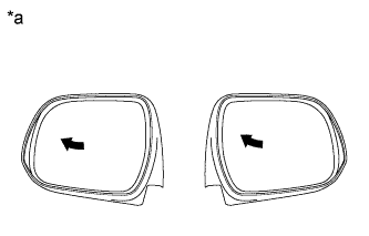 |
Turn the power switch on (IG).
Using the outer mirror switch assembly, turn the mirror surface to the fully left position.
| *a | Turn to Left Fully |
Press the M1 switch while the SET switch is being pressed.
Check that the buzzer sounds for 0.5 seconds and the mirror surface position is memorized.
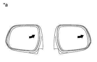 |
Using the outer mirror switch assembly, turn the mirror surface to the fully right position.
| *a | Turn to Right Fully |
Press the M1 switch.
Check that the buzzer sounds for 0.1 seconds and the outer mirror automatically moves to the recorded fully left position.
|
| ||||
| OK | |
|
| 19.REPLACE OUTER MIRROR CONTROL ECU ASSEMBLY |
Replace the outer mirror control ECU assembly (Click here).
| NEXT | |
|
| 20.CHECK AUTOMATIC MEMORY CALL FUNCTION |
Perform registration for automatic memory call function (Click here).
Perform a wireless door unlock operation and check that opening the driver side door causes the following:
|
| ||||
| OK | ||
| ||
| ||
| 21.READ VALUE USING INTELLIGENT TESTER (DOOR COURTESY SWITCH) |
Connect the intelligent tester to the DLC3.
Turn the power switch on (IG).
Turn the intelligent tester on.
Enter the following menus: Body / Main Body / Data List.
Read the Data List according to the display on the intelligent tester.
| Tester Display | Measurement Item/Range | Normal Condition | Diagnostic Note |
| FL Door Courtesy | Driver door courtesy switch condition/ON or OFF | ON: Door courtesy switch on (driver door open) OFF: Door courtesy switch off (driver door closed) | - |
|
| ||||
| OK | |
|
| 22.REPLACE MAIN BODY ECU (MULTIPLEX NETWORK BODY ECU) |
Replace the main body ECU (multiplex network body ECU) (Click here).
| NEXT | |
|
| 23.CHECK AUTOMATIC MEMORY CALL FUNCTION |
Perform registration for automatic memory call function (Click here).
Perform a wireless door unlock operation and check that opening the driver side door causes the following:
|
| ||||
| OK | ||
| ||
| ||
| 24.CHECK ELECTRICAL REMOTE CONTROL MIRROR FUNCTION |
Check electrical remote control mirror function (Click here).
|
| ||||
| OK | ||
| ||
| ||


