DTC B15D0 MOST Communication Malfunction |
| DTC No. | DTC Detection Condition | Trouble Area |
| B15D0 | MOST network cannot be established. |
|
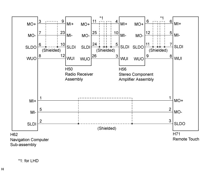
| 1.CONFIRM MODEL |
Choose the model to be inspected.
| Model | Proceed to |
| for 13 speakers | A |
| except 13 speakers | B |
|
| ||||
| A | |
 |
| 2.CONFIRM SYMPTOMS |
Power switch off.
Turn the power switch on (ACC) and check if the audio system activates and if the speakers operate.
| Model | Proceed to |
| The audio system activates when the power switch is turned on (ACC) but the sound stops being output when the amplifier output exceeds a certain level. | A |
| Even after the power switch is turned on (ACC), the audio system does not activate and sound is not output from the speakers. | B |
|
| ||||
| A | ||
 | ||
| ||
| 3.PERFORM MOST LINE CHECK |
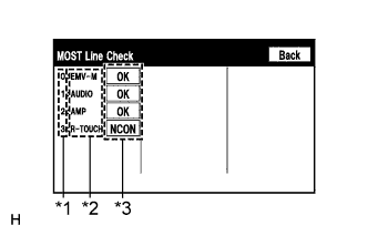 |
Display the "MOST Line Check" screen (Click here).
Check the result on the "MOST Line Check" screen.
| Result | Proceed to |
| "NCON" is displayed for "AUDIO". | A |
| "NCON" is displayed for "AMP". | B |
| "NCON" is displayed for "R-TOUCH". | C |
| "OK" is displayed for all items. | D |
| *1 | Node position number for devices that use MOST communication |
| *2 | Device name |
| *3 | Result |
|
| ||||
|
| ||||
|
| ||||
| A | |
|
| 4.CHECK MOST COMMUNICATION CONNECTORS |
Check the MOST communication line connectors.
Check if the MOST communication line connector between the navigation computer sub-assembly and radio receiver assembly has any connection problems (Click here).
Display the "MOST Line Check" screen and check the result (Click here).
| Result | Proceed to |
| "NCON" is displayed for "AUDIO". | A |
| The screen cannot be changed to the "MOST Line Check" screen. | B |
|
| ||||
| A | |
|
| 5.CHECK HARNESS AND CONNECTOR (WAKE-UP SIGNAL) |
Disconnect the H50 radio receiver assembly connector.
Measure the voltage according to the value(s) in the table below.
| Tester Connection | Condition | Specified Condition |
| H50-12 (WUI) - Body ground | Power switch on (ACC) | 4.5 V or higher |
|
| ||||
| OK | ||
| ||
| ||
| 6.CHECK HARNESS AND CONNECTOR |
Disconnect the H50 radio receiver assembly connector.
Disconnect the H62 navigation computer sub-assembly connector.
Measure the resistance according to the value(s) in the table below.
| Tester Connection | Condition | Specified Condition |
| H50-12 (WUI) - H62-8 (WUO) | Always | Below 1 Ω |
| H50-12 (WUI) - Body ground | Always | 10 kΩ or higher |
|
| ||||
| OK | ||
| ||
| ||
| 7.CHECK MOST COMMUNICATION CONNECTORS |
Check the MOST communication line connectors.
Check if the MOST communication line connector between the radio receiver assembly and stereo component amplifier assembly has any connection problems (Click here).
Display the "MOST Line Check" screen and check the result (Click here).
| Result | Proceed to |
| "NCON" is displayed for "AMP". | A |
| The screen cannot be changed to the "MOST Line Check" screen. | B |
|
| ||||
| A | |
|
| 8.CHECK HARNESS AND CONNECTOR (WAKE-UP SIGNAL) |
Disconnect the H56 stereo component amplifier assembly connector.
Measure the voltage according to the value(s) in the table below.
| Tester Connection | Condition | Specified Condition |
| H56-3 (WUI) - Body ground | Power switch on (ACC) | 4.5 V or higher |
|
| ||||
| OK | ||
| ||
| ||
| 9.CHECK HARNESS AND CONNECTOR |
Disconnect the H56 stereo component amplifier assembly connector.
Disconnect the H50 radio receiver assembly connector.
Measure the resistance according to the value(s) in the table below.
| Tester Connection | Condition | Specified Condition |
| H56-3 (WUI) - H50-26 (WUO) | Always | Below 1 Ω |
| H56-3 (WUI) - Body ground | Always | 10 kΩ or higher |
|
| ||||
| OK | ||
| ||
| ||
| 10.CHECK MOST COMMUNICATION CONNECTORS |
Check the MOST communication line connectors.
Check if the MOST communication line connector between the stereo component amplifier assembly and remote touch has any connection problems (Click here).
Display the "MOST Line Check" screen and check the result (Click here).
| Result | Proceed to |
| "NCON" is displayed for "R-TOUCH". | A |
| The screen cannot be changed to the "MOST Line Check" screen. | B |
|
| ||||
| A | |
|
| 11.CHECK HARNESS AND CONNECTOR (WAKE-UP SIGNAL) |
Disconnect the H71 remote touch connector.
Measure the voltage according to the value(s) in the table below.
| Tester Connection | Condition | Specified Condition |
| H71-8 (WUI) - Body ground | Power switch on (ACC) | 4.5 V or higher |
|
| ||||
| OK | ||
| ||
| ||
| 12.CHECK HARNESS AND CONNECTOR |
Disconnect the H71 remote touch connector.
Disconnect the H56 stereo component amplifier assembly connector.
Measure the resistance according to the value(s) in the table below.
| Tester Connection | Condition | Specified Condition |
| H71-8 (WUI) - H56-9 (WUO) | Always | Below 1 Ω |
| H71-8 (WUI) - Body ground | Always | 10 kΩ or higher |
|
| ||||
| OK | ||
| ||
| ||
| 13.CHECK HARNESS AND CONNECTOR |
Disconnect the H62 navigation computer sub-assembly connector.
Disconnect the H50 radio receiver assembly connector.
Measure the resistance according to the value(s) in the table below.
| Tester Connection | Condition | Specified Condition |
| H62-3 (MO+) - H50-9 (MI+) | Always | Below 1 Ω |
| H62-7 (MO-) - H50-23 (MI-) | Always | Below 1 Ω |
| H62-6 (SLDO) - H50-10 (SLDI) | Always | Below 1 Ω |
| H62-8 (WUO) - H50-12 (WUI) | Always | Below 1 Ω |
| H62-3 (MO+) - Body ground | Always | 10 kΩ or higher |
| H62-7 (MO-) - Body ground | Always | 10 kΩ or higher |
| H62-6 (SLDO) - Body ground | Always | 10 kΩ or higher |
| H62-8 (WUO) - Body ground | Always | 10 kΩ or higher |
|
| ||||
| OK | |
|
| 14.CHECK HARNESS AND CONNECTOR |
Disconnect the H50 radio receiver assembly connector.
Disconnect the H56 stereo component amplifier assembly connector.
Measure the resistance according to the value(s) in the table below.
| Tester Connection | Condition | Specified Condition |
| H50-11 (MO+) - H56-4 (MI+) | Always | Below 1 Ω |
| H50-25 (MO-) - H56-10 (MI-) | Always | Below 1 Ω |
| H50-24 (SLDI) - H56-5 (SLDI) | Always | Below 1 Ω |
| H50-26 (WUO) - H56-3 (WUI) | Always | Below 1 Ω |
| H50-11 (MO+) - Body ground | Always | 10 kΩ or higher |
| H50-25 (MO-) - Body ground | Always | 10 kΩ or higher |
| H50-24 (SLDI) - Body ground | Always | 10 kΩ or higher |
| H50-26 (WUO) - Body ground | Always | 10 kΩ or higher |
|
| ||||
| OK | |
|
| 15.CHECK HARNESS AND CONNECTOR |
Disconnect the H56 stereo component amplifier assembly connector.
Disconnect the H71 remote touch connector.
Measure the resistance according to the value(s) in the table below.
| Tester Connection | Condition | Specified Condition |
| H56-6 (MO+) - H71-6 (MI+) | Always | Below 1 Ω |
| H56-12 (MO-) - H71-5 (MI-) | Always | Below 1 Ω |
| H56-11 (SLDO) - H71-7 (SLDI) | Always | Below 1 Ω |
| H56-9 (WUO) - H71-8 (WUI) | Always | Below 1 Ω |
| H56-6 (MO+) - Body ground | Always | 10 kΩ or higher |
| H56-12 (MO-) - Body ground | Always | 10 kΩ or higher |
| H56-11 (SLDO) - Body ground | Always | 10 kΩ or higher |
| H56-9 (WUO) - Body ground | Always | 10 kΩ or higher |
|
| ||||
| OK | |
|
| 16.CHECK HARNESS AND CONNECTOR |
Disconnect the H71 remote touch connector.
Disconnect the H62 navigation computer sub-assembly connector.
Measure the resistance according to the value(s) in the table below.
| Tester Connection | Condition | Specified Condition |
| H71-1 (MO+) - H62-1 (MI+) | Always | Below 1 Ω |
| H71-2 (MO-) - H62-5 (MI-) | Always | Below 1 Ω |
| H71-3 (SLDO) - H62-2 (SLDI) | Always | Below 1 Ω |
| H71-1 (MO+) - Body ground | Always | 10 kΩ or higher |
| H71-2 (MO-) - Body ground | Always | 10 kΩ or higher |
| H71-3 (SLDO) - Body ground | Always | 10 kΩ or higher |
|
| ||||
| OK | |
|
| 17.REPLACE REMOTE OPERATION BOARD |
Replace the remote operation board (Click here).
Clear the DTCs (Click here).
Recheck for DTCs and check if the same DTCs are output again.
| Result | Proceed to |
| No DTCs are output. | A |
| DTCs are output. | B |
|
| ||||
| A | ||
| ||
| ||
| 18.REPLACE STEREO COMPONENT AMPLIFIER ASSEMBLY |
Replace the stereo component amplifier assembly (Click here).
Clear the DTCs (Click here).
Recheck for DTCs and check if the same DTCs are output again.
| Result | Proceed to |
| No DTCs are output. | A |
| DTCs are output. | B |
|
| ||||
| A | ||
| ||
| ||
| 19.REPLACE RADIO RECEIVER ASSEMBLY |
Replace the radio receiver assembly (Click here).
Clear the DTCs (Click here).
Recheck for DTCs and check if the same DTCs are output again.
| Result | Proceed to |
| No DTCs are output. | A |
| DTCs are output. | B |
|
| ||||
| A | ||
| ||
| ||


