DTC B1569 DVD-ROM Deck Disconnected |
| DTC No. | DTC Detection Condition | Trouble Area |
| B1569 | When either of the conditions below is met:
|
|
| 1.CHECK OPTIONAL COMPONENTS (INCLUDING ASSOCIATED WIRING) |
Check for optional components.
Check that optional components (including associated wiring) which generate radio waves are not installed.
| Result | Proceed to |
| Optional components (including associated wiring) are installed. | A |
| Optional components (including associated wiring) are not installed. | B |
|
| ||||
| A | |
 |
| 2.REMOVE OPTIONAL COMPONENTS (INCLUDING ASSOCIATED WIRING) |
Remove optional components (including associated wiring).
| NEXT | |
|
| 3.CHECK DTC |
Clear the DTCs (Click here).
Recheck for DTCs and check if the same DTC is output again.
|
| ||||
| OK | ||
 | ||
| ||
| 4.CHECK HARNESS AND CONNECTOR (NAVIGATION MODULE BOARD POWER SOURCE) |
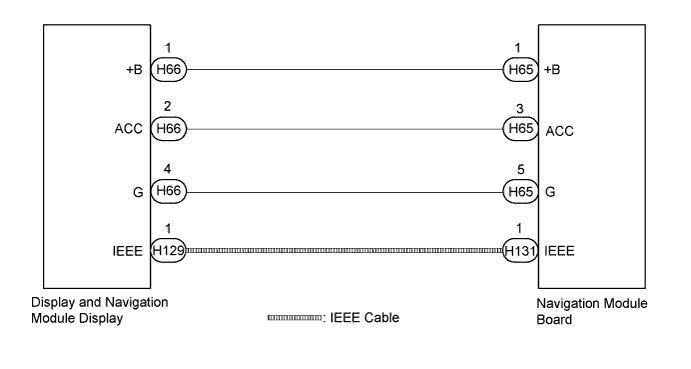
Disconnect the H65 navigation module board connector.
Measure the resistance according to the value(s) in the table below.
| Tester Connection | Condition | Specified Condition |
| H65-5 (G) - Body ground | Always | Below 1 Ω |
Measure the voltage according to the value(s) in the table below.
| Tester Connection | Condition | Specified Condition |
| H65-1 (+B) - H65-5 (G) | Power switch off | 11 to 14 V |
| H65-3 (ACC) - H65-5 (G) | Power switch on (ACC) | 11 to 14 V |
|
| ||||
| OK | |
|
| 5.CHECK IEEE CABLE CONNECTOR |
Check the IEEE cable connectors.
Check if the IEEE cable connectors between the navigation module board and the display and navigation module display have any connection problems (Click here).
Check that the screen display is normal.
|
| ||||
| OK | ||
| ||
| ||
| 6.REPLACE IEEE CABLE |
Replace the IEEE cable between the navigation module board and the display and navigation module display.
Check that the screen display is normal.
|
| ||||
| OK | ||
| ||
| ||
| 7.REPLACE NAVIGATION MODULE BOARD |
Replace the navigation module board (Click here).
Clear the DTCs (Click here).
Recheck for DTCs and check if the same DTC is output again.
|
| ||||
| OK | ||
| ||
| ||
| 8.CHECK HARNESS AND CONNECTOR |
Disconnect the H66 display and navigation module display connector.
Disconnect the H65 navigation module board connector.
Measure the resistance according to the value(s) in the table below.
| Tester Connection | Condition | Specified Condition |
| H66-1 (+B) - H65-1 (+B) | Always | Below 1 Ω |
| H66-2 (ACC) - H65-3 (ACC) | Always | Below 1 Ω |
| H66-4 (G) - H65-5 (G) | Always | Below 1 Ω |
| H66-1 (+B) - Body ground | Always | 10 kΩ or higher |
| H66-2 (ACC) - Body ground | Always | 10 kΩ or higher |
| H66-4 (G) - Body ground | Always | 10 kΩ or higher |
|
| ||||
| OK | ||
| ||
| ||


