NAVIGATION SYSTEM (for HDD) > Switch Lights of Remote Touch do not Illuminate |
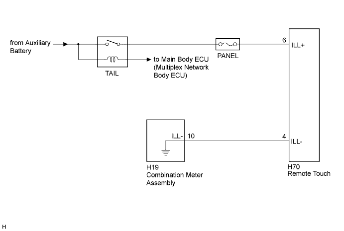
| 1.CONFIRM SYMPTOMS |
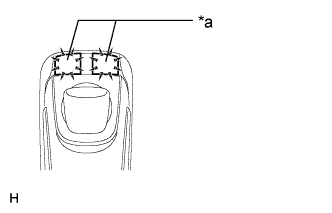 |
Perform the following settings and check the switch illumination again.
When the vehicle is in a bright area, move to a dark area.
Set the rheostat to the maximum brightness.
If the light control switch is in the AUTO position, turn the switch to the tail or head position.
| *a | Switch Illumination |
|
| ||||
| OK | ||
 | ||
| ||
| 2.REMOTE TOUCH SELF CHECK (SWITCH ILLUMINATION CHECK) |
Activate self check mode (Click here).
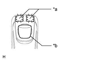 |
Check switch illumination.
Move the remote touch switch knob from the lower left to the upper right to check that the brightness of the switch illumination changes.
| *a | Switch Illumination |
| *b | Switch Knob |
|
| ||||
| OK | |
 |
| 3.CHECK HARNESS AND CONNECTOR (ILLUMINATION SIGNAL) |
Disconnect the H70 remote touch connector.
Measure the voltage according to the value(s) in the table below.
| Tester Connection | Condition | Specified Condition |
| H70-6 (ILL+) - Body ground | Light control switch in the tail or head position | 11 to 14 V |
|
| ||||
| OK | |
|
| 4.CHECK HARNESS AND CONNECTOR |
Disconnect the H70 remote touch connector.
Disconnect the H19 combination meter assembly connector.
Measure the resistance according to the value(s) in the table below.
| Tester Connection | Condition | Specified Condition |
| H70-4 (ILL-) - H19-10 (ILL-) | Always | Below 1 Ω |
| H70-4 (ILL-) - Body ground | Always | 10 kΩ or higher |
|
| ||||
| OK | |
|
| 5.REPLACE REMOTE OPERATION BOARD |
Replace the remote operation board (Click here).
Check if the switch illumination turns on.
|
| ||||
| OK | ||
| ||
| ||
| 6.REPLACE INTEGRATION PANEL SUB-ASSEMBLY |
Replace the integration panel sub-assembly (Click here).
Check if the switch illumination turns on.
|
| ||||
| OK | ||
| ||
| ||


