NAVIGATION SYSTEM (for HDD) > Switch Lights of Remote Touch Always Illuminate or cannot be Controlled Using Rheostat |
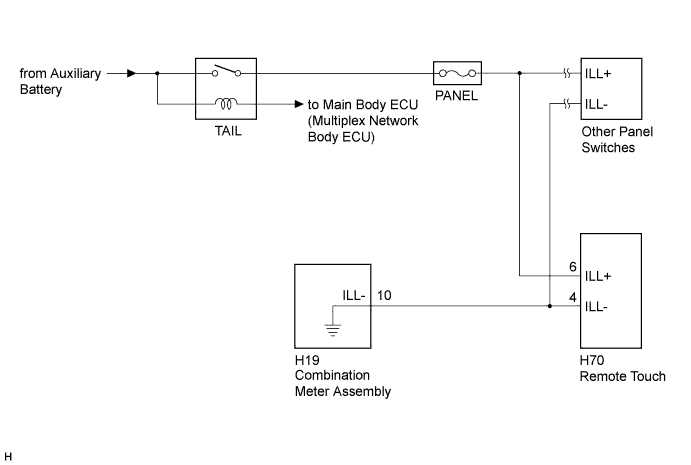
| 1.CHECK ILLUMINATION CONTROLLED BY RHEOSTAT SWITCH |
Perform the following and check that the illumination controlled by the rheostat switch illuminates properly.
If the vehicle is in a bright area, move it to a dark area.
If the light control switch is in the AUTO position, turn the switch to the tail or head position.
| Result | Proceed to |
| Any of the illumination controlled by the rheostat switch does not illuminate properly. | A |
| All of the illumination controlled by the rheostat switch illuminates properly. | B |
|
| ||||
| A | |
 |
| 2.REPAIR OR REPLACE ILLUMINATION CONTROLLED BY RHEOSTAT SWITCH |
Repair or replace the part with the malfunctioning illumination that is controlled by the rheostat switch.
| NEXT | |
|
| 3.CONFIRM SYMPTOMS |
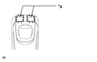 |
Perform the following settings, operate the rheostat switch again, and check if illumination brightness adjustment is possible (including adjustment of other devices such as the radio receiver assembly).
Check if the remote touch is in self check mode. If it is, cancel self check mode (Click here).
If the vehicle is in a bright area, move it to a dark area.
If the light control switch is in the AUTO position, turn the switch to the tail or head position.
| Result | Proceed to |
| Switch illumination cannot be adjusted (illumination for other devices can be adjusted). | A |
| Switch illumination cannot be adjusted (illumination for other devices also cannot be adjusted). | B |
| Switch illumination can be adjusted. | C |
| *a | Switch Illumination |
|
| ||||
|
| ||||
| A | |
|
| 4.REMOTE TOUCH SELF CHECK (SWITCH ILLUMINATION CHECK) |
Activate self check mode (Click here).
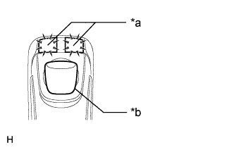 |
Check the switch illumination.
Move the remote touch switch knob from the lower left to the upper right to check that the brightness of the switch illumination changes.
| *a | Switch Illumination |
| *b | Switch Knob |
|
| ||||
| OK | |
|
| 5.CHECK HARNESS AND CONNECTOR (ILLUMINATION SIGNAL) |
Disconnect the H70 remote touch connector.
Measure the voltage according to the value(s) in the table below.
| Tester Connection | Condition | Specified Condition |
| H70-6 (ILL+) - Body ground | Light control switch in the tail or head position | 11 to 14 V |
|
| ||||
| OK | |
|
| 6.CHECK HARNESS AND CONNECTOR |
Disconnect the H70 remote touch connector.
Disconnect the H19 combination meter assembly connector.
Measure the resistance according to the value(s) in the table below.
| Tester Connection | Condition | Specified Condition |
| H70-4 (ILL-) - H19-10 (ILL-) | Always | Below 1 Ω |
| H70-4 (ILL-) - Body ground | Always | 10 kΩ or higher |
|
| ||||
| OK | ||
 | ||
| ||


