AUDIO AND VISUAL SYSTEM (w/o Navigation System) > USB Audio System Recognition/Play Error |
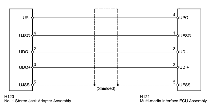
| for 10 Speakers |
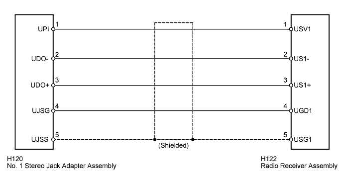
| for 6 Speakers |
| 1.CHECK USB DEVICE OR "iPod" |
Disconnect the USB device or "iPod" from the No. 1 stereo jack adapter assembly.
Check if playable files are present on the USB device or "iPod".
Check if the USB device is a compatible format or "iPod" is a compatible version.
| Condition | Proceed to |
| No playable files exist, or incompatible device format or version | A |
| Playable files exist, and compatible device format or version | B |
|
| ||||
| A | ||
 | ||
| ||
| 2.CHECK HARNESS AND CONNECTOR |
Disconnect the multi-media interface ECU assembly*1 or radio receiver assembly*2 and No. 1 stereo jack adapter assembly connectors.
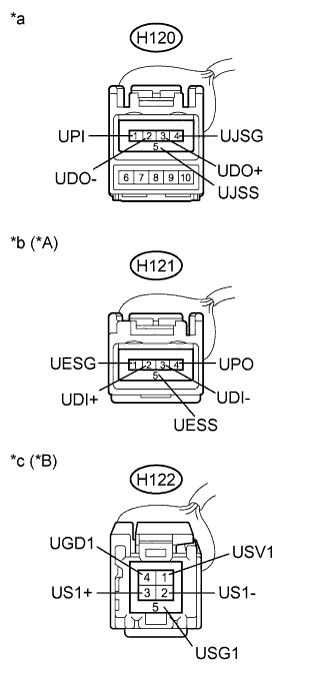 |
Measure the resistance according to the value(s) in the table below.
| Tester Connection | Condition | Specified Condition |
| H120-1 (UPI) - H121-4 (UPO) | Always | Below 1 Ω |
| H120-4 (UJSG) - H121-1 (UESG) | Always | Below 1 Ω |
| H120-2 (UDO-) - H121-3 (UDI-) | Always | Below 1 Ω |
| H120-3 (UDO+) - H121-2 (UDI+) | Always | Below 1 Ω |
| H120-5 (UJSS) - H121-5 (UESS) | Always | Below 1 Ω |
| H120-1 (UPI) - Body ground | Always | 10 kΩ or higher |
| H120-4 (UJSG) - Body ground | Always | 10 kΩ or higher |
| H120-2 (UDO-) - Body ground | Always | 10 kΩ or higher |
| H120-3 (UDO+) - Body ground | Always | 10 kΩ or higher |
| H120-5 (UJSS) - Body ground | Always | 10 kΩ or higher |
| Tester Connection | Condition | Specified Condition |
| H120-1 (UPI) - H122-1 (USV1) | Always | Below 1 Ω |
| H120-2 (UDO-) - H122-2 (US1-) | Always | Below 1 Ω |
| H120-3 (UDO+) - H122-3 (US1+) | Always | Below 1 Ω |
| H120-4 (UJSG) - H122-4 (UGD1) | Always | Below 1 Ω |
| H120-5 (UJSS) - H122-5 (USG1) | Always | Below 1 Ω |
| H120-1 (UPI) - Body ground | Always | 10 kΩ or higher |
| H120-2 (UDO-) - Body ground | Always | 10 kΩ or higher |
| H120-3 (UDO+) - Body ground | Always | 10 kΩ or higher |
| H120-4 (UJSG) - Body ground | Always | 10 kΩ or higher |
| H120-5 (UJSS) - Body ground | Always | 10 kΩ or higher |
| *A | for 10 Speakers |
| *B | for 6 Speakers |
| *a | Front view of wire harness connector (to No. 1 Stereo Jack Adapter Assembly) |
| *b | Front view of wire harness connector (to Multi-media Interface ECU Assembly) |
| *c | Front view of wire harness connector (to Radio Receiver Assembly) |
|
| ||||
| OK | |
 |
| 3.CHECK POWER SOURCE |
Reconnect the multi-media interface ECU assembly*1 connector or radio receiver assembly*2 connector.
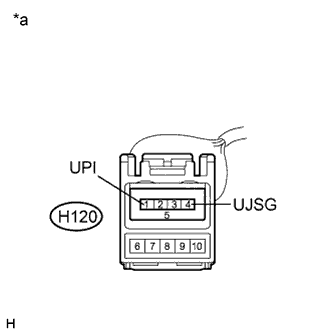 |
Measure the voltage according to the value(s) in the table below.
| Tester Connection | Condition | Specified Condition |
| H120-1 (UPI) - H120-4 (UJSG) | Power switch on (ACC) | 5 V |
Proceed to the next step based on the inspection result.
| Condition | Proceed to |
| OK | A |
| NG (for 10 Speakers) | B |
| NG (for 6 Speakers) | C |
| *a | Front view of wire harness connector (to No. 1 Stereo Jack Adapter Assembly) |
|
| ||||
|
| ||||
| A | |
|
| 4.FORMAT USB DEVICE OR RESTORE "iPod" AND RECHECK |
Delete all files in the USB device or "iPod" and format/restore it.
Save the data again and check if it can be played on the in-vehicle device.
|
| ||||
| OK | ||
| ||
| ||
| 5.REPLACE USB DEVICE OR "iPod" |
Turn the power switch off.
Turn the power switch on (ACC).
Connect a known good USB device or "iPod" to the No. 1 stereo jack adapter assembly.
| NEXT | |
|
| 6.CHECK USB DEVICE OR "iPod" |
Check if the USB device or "iPod" is recognized by the radio receiver assembly, or if information such as track, artist and album names are displayed on the screen.
|
| ||||
| OK | ||
| ||
| ||


