Cylinder Head Cover Sub-assembly
A lightweight and high-strength aluminum die-cast cylinder head cover sub-assembly is used.
An oil delivery pipe is installed inside the cylinder head cover sub-assembly. This ensures lubrication to the sliding parts of the roller rocker arms, improving reliability.
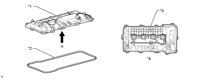
Text in Illustration *1 Cylinder Head Cover Sub-assembly *2 Cylinder Head Cover Gasket *3 Oil Delivery Pipe - - *a View from A - -
Cylinder Head Sub-assembly
The cylinder head structure has been simplified by separating the camshaft housing (cam journal portion) from the cylinder head sub-assembly.
The cylinder head sub-assembly, which is made of aluminum, contains a pentroof type combustion chamber. The spark plug is located in the center of the combustion chamber in order to improve the engine's anti-knocking performance.
The angle of the intake and exhaust valves has been narrowed and set at 29° to permit a compact cylinder head sub-assembly.
Thin-electrode type spark plugs with a 12 mm (0.47 in.) diameter threaded base are used in order to make it possible to increase the diameter of the intake and exhaust valves. As a result, improved intake and exhaust efficiency has been realized.
A taper squish combustion chamber is used to improve anti-knocking performance and intake efficiency. In addition, engine performance and fuel economy have been improved.
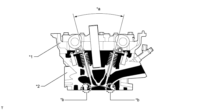
Text in Illustration *1 Camshaft Housing *2 Cylinder Head Sub-assembly *a 29° *b Taper Squish Siamese type intake ports are used to reduce the overall surface area of the intake port walls. This helps prevent fuel from adhering to the intake port walls, thus reducing HC exhaust emissions.
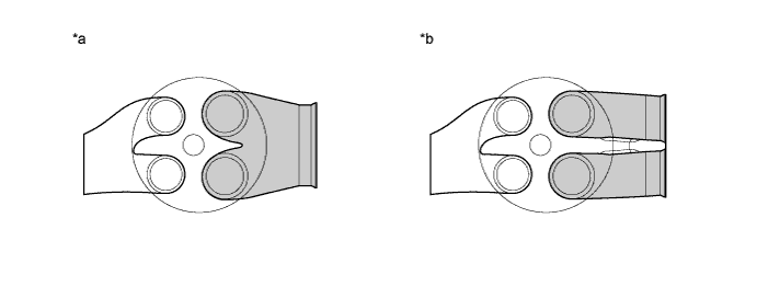
Text in Illustration *a Siamese Type *b Independent Type
Cylinder Block Sub-assembly
A spiny type liner, which has an irregularly shaped outer casting surface, is used to enhance the adhesion between the liners and the aluminum of the cylinder block sub-assembly. The enhanced adhesion helps heat dissipation, resulting in a lower overall temperature and reduced heat deformation of the cylinder bores. A cylinder block with this type of liner cannot be rebored.
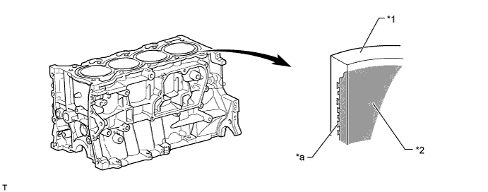
Text in Illustration *1 Cylinder Block Sub-assembly *2 Spiny-type Liner *a Irregularly shaped outer casting surface of liner - - Through the use of an offset crankshaft, the centerline of the cylinder bores is shifted 8 mm (0.31 in.) towards the exhaust in relation to the centerline of the crankshaft. Thus, the side force (thrust) applied to the cylinder walls is reduced when maximum combustion pressure is applied. This contributes to fuel economy.
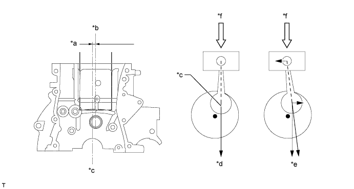
Text in Illustration *a 8 mm (0.31 in.) *b Bore Centerline *c Crankshaft Centerline *d Offset Crankshaft *e Non-offset Crankshaft *f Maximum Pressure
Oil Pan Sub-assembly
A lightweight and high-strength aluminum die-cast oil pan is used.
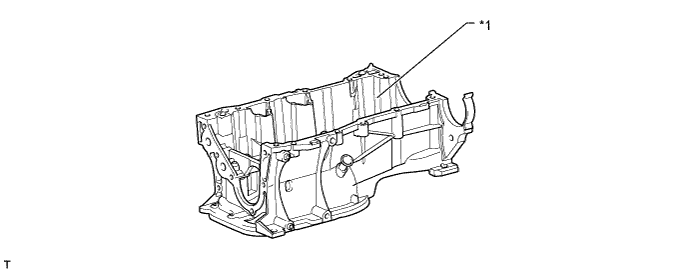
Text in Illustration *1 Oil Pan Sub-assembly (Stiffening Crankcase Assembly) - -
Piston
The pistons are made of aluminum alloy to allow them to be compact and lightweight.
The top of the piston uses a taper squish shape to achieve fuel combustion efficiency.
The piston skirt is coated with resin to reduce friction losses.
Full floating type piston pins are used.
Narrow-width piston rings are used to reduce weight and friction.
Low-tension piston rings are used to reduce friction and achieve excellent fuel economy.
A No. 1 compression ring with an inside bevel shape is used to reduce blowby.
A steel No. 2 compression ring is used to improve wear resistance.
A Physical Vapor Deposition (PVD) coating has been applied to the surface of the No. 1 compression ring and oil ring, in order to improve wear resistance.
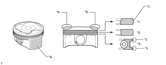
Text in Illustration *1 No. 1 Compression Ring *2 No. 2 Compression Ring *3 Oil Ring - - *a Resin Coating *b Taper Squish Shape *c PVD Coating - -
Connecting Rod Sub-assembly and Connecting Rod Bearing
The connecting rods are made of high-strength steel for weight reduction.
The width of the connecting rod bearings has been optimized to reduce friction.
The lining surface of the connecting rod bearing is micro-grooved to provide an optimal oil clearance. As a result, cold-engine cranking performance has been improved and engine vibration has been reduced.
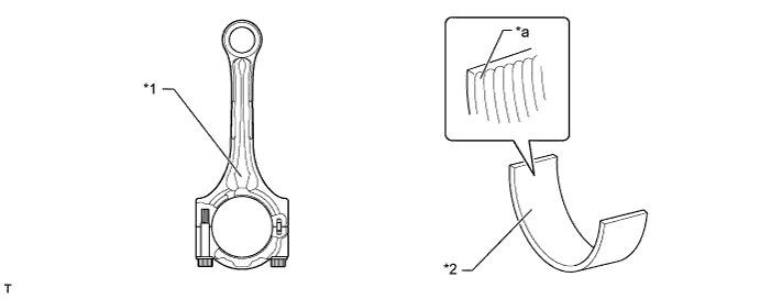
Text in Illustration *1 Connecting Rod Sub-assembly *2 Connecting Rod Bearing *a Micro-grooved - -
Crankshaft and Crankshaft Bearing
The crankshaft has 5 main journals and 8 balance weights.
The pins and journals have been machined with increased precision and the surface roughness has been minimized to reduce friction.
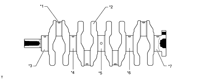
Text in Illustration *1 Oil Hole *2 Balance Weight *3 No. 1 Journal *4 No. 2 Journal *5 No. 3 Journal *6 No. 4 Journal *7 No. 5 Journal - - The width of the crankshaft bearings has been optimized to reduce friction.
The lining surface of the crankshaft bearing is micro-grooved to provide an optimal oil clearance. As a result, cold-engine cranking performance has been improved and engine vibration has been reduced.
An oil groove is provided on each upper main bearing (crankshaft bearing). The oil groove is deep at the center and is shallow at the edges to reduce the amount of oil that will leak from the crankshaft bearing. As a result, the size of the oil pump has been reduced, thus minimizing friction.
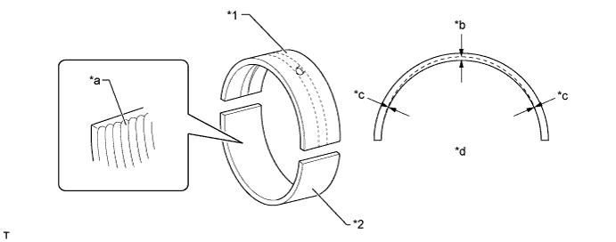
Text in Illustration *1 Upper Main Bearing (Crankshaft Bearing) *2 Lower Main Bearing (Crankshaft Bearing) *a Micro-grooved *b Center *c Edge *d Oil Groove Depth
Valve Mechanism
The 2ZR-FXE engine is a high-expansion ratio Atkinson cycle engine of which the intake valve close timing has been significantly retarded by setting the camshaft timing gear assembly (VVT-i controller) and camshaft (intake camshaft) to the retard side.
Each cylinder is equipped with 2 intake valves and 2 exhaust valves. Intake and exhaust efficiency has been increased due to the larger total port areas.
The valve mechanism uses a roller rocker arm with built-in needle bearings. This reduces the friction that occurs between the cams and the areas on the roller rocker arms that push the valves down, thus improving fuel economy.
Hydraulic valve lash adjusters, which maintain a constant zero valve clearance through the use of oil pressure and spring force, are used.
The camshaft (intake camshaft) and No. 2 camshaft (exhaust camshaft) are driven by a chain sub-assembly (timing chain).
The Variable Valve Timing-intelligent (VVT-i) system is used to achieve low fuel consumption, high engine performance and reduce exhaust emissions.
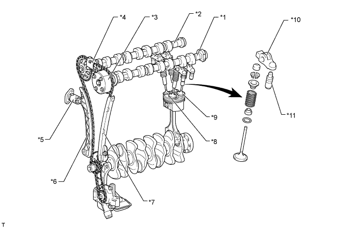
Text in Illustration *1 Camshaft (Intake Camshaft) *2 No. 2 Camshaft (Exhaust Camshaft) *3 Camshaft Timing Gear Assembly (VVT-i Controller) *4 Chain Vibration Damper No. 2 *5 Chain Tensioner Assembly *6 Chain Tensioner Slipper *7 Chain Vibration Damper No. 1 *8 Exhaust Valve *9 Intake Valve *10 Roller Rocker Arm *11 Hydraulic Valve Lash Adjuster Assembly - -
Camshaft
Oil passages are provided in the camshaft (intake camshaft) in order to supply engine oil pressure to the VVT-i system.
A camshaft timing gear assembly (VVT-i controller) is installed on the front of the camshaft (intake camshaft) to vary the timing of the intake valves.
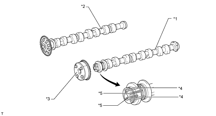
Text in Illustration *1 Camshaft (Intake Camshaft) *2 No. 2 Camshaft (Exhaust Camshaft) *3 Camshaft Timing Gear Assembly (VVT-i Controller) *4 Oil Passage (Advance) *5 Oil Passage (Retard) - -
Camshaft Timing Gear Assembly (VVT-i Controller)
This camshaft timing gear assembly (VVT-i controller) consists of the housing driven from the timing chain and the vane coupled with the camshaft (intake camshaft).
The oil pressure sent from the advance or retard side path at the intake camshaft causes rotation in the camshaft timing gear assembly (VVT-i controller) vane circumferential direction to vary the intake valve timing continuously.
When the engine is stopped, the camshaft (intake camshaft) will be in the most retarded state to ensure startability.
When hydraulic pressure is not applied to the camshaft timing gear assembly (VVT-i controller) immediately after the engine has been started, the lock pin locks the movement of the camshaft timing gear assembly (VVT-i controller) to prevent a knocking noise.
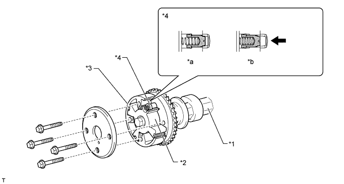
Text in Illustration *1 Camshaft (Intake Camshaft) *2 Vane (Fixed on Intake Camshaft) *3 Housing *4 Lock Pin *a Engine Stopped *b Engine Operating 
Oil Pressure - -
Hydraulic Valve Lash Adjuster Assembly
A hydraulic valve lash adjuster assembly is located at the fulcrum of each roller rocker arm. A hydraulic valve lash adjuster assembly consists primarily of a plunger, a plunger spring, a check ball, and a check ball spring.
The hydraulic valve lash adjuster assembly is actuated by the engine oil, plunger spring, and check ball spring. The oil pressure and the spring force that act on the plunger push the roller rocker arm against the cam, in order to adjust the valve clearance. This reduces the engine noise that is created during the opening and closing of the valves.
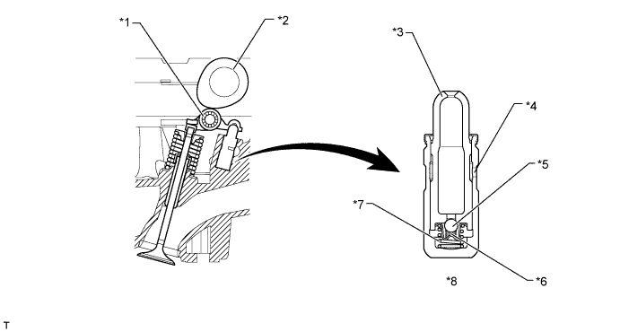
Text in Illustration *1 Roller Rocker Arm *2 Cam *3 Plunger *4 Oil Passage *5 Check Ball *6 Check Ball Spring *7 Plunger Spring *8 Hydraulic Valve Lash Adjuster Assembly - HINT:
- Valve clearance adjustment is not necessary because hydraulic valve lash adjusters are used.
Chain Sub-assembly (Timing Chain) and Chain Tensioner Assembly
A chain sub-assembly (timing chain) with an 8 mm (0.31 in.) pitch is used to make the engine more compact.
The chain tensioner uses a spring and oil pressure to maintain proper chain tension at all times.
The chain tensioner suppresses noise generated by the chain sub-assembly (timing chain).
The chain tensioner is a ratcheting type tensioner with a non-return mechanism.
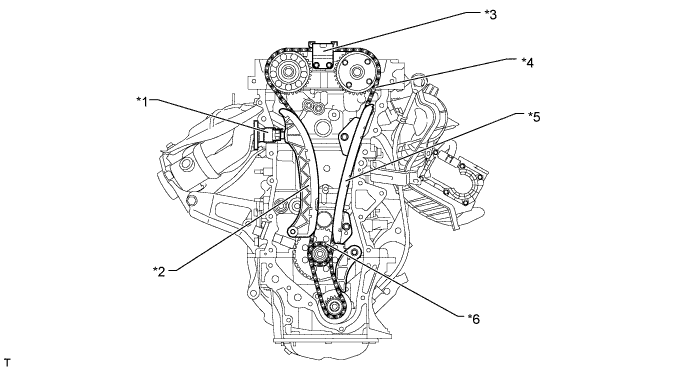
Text in Illustration *1 Chain Tensioner Assembly *2 Chain Tensioner Slipper *3 Chain Vibration Damper No. 2 *4 Chain Sub-assembly *5 Chain Vibration Damper No. 1 *6 Crankshaft Timing Sprocket