FUEL SYSTEM > DETAILS


FUNCTION


  1. Fuel Returnless System


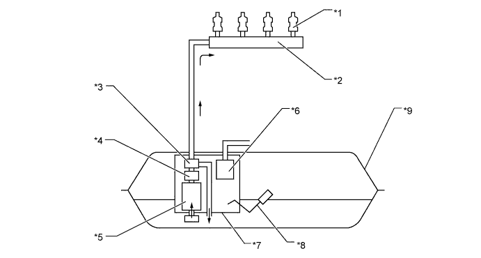
    1. This system is used to reduce evaporative emissions. As shown below, by integrating the fuel filter, fuel pressure regulator, charcoal canister, fuel sender gauge, and fuel pump, it is possible to discontinue the return of fuel from the engine area, thus preventing temperature rise inside the fuel tank assembly. This reduces the generation of evaporative emissions in the fuel tank assembly.

      W101567E01


      Text in Illustration 
      *1
      Fuel Injector Assembly
      *2
      Fuel Delivery Pipe Sub-assembly
      *3
      Fuel Pressure Regulator Assembly
      *4
      Fuel Filter
      *5
      Fuel Pump
      *6
      Charcoal Canister
      *7
      Fuel Suction with Pump and Gauge Tube Assembly
      *8
      Fuel Sender Gauge Assembly
      *9
      Fuel Tank Assembly
      -
      -

CONSTRUCTION


  1. Fuel Tank Assembly

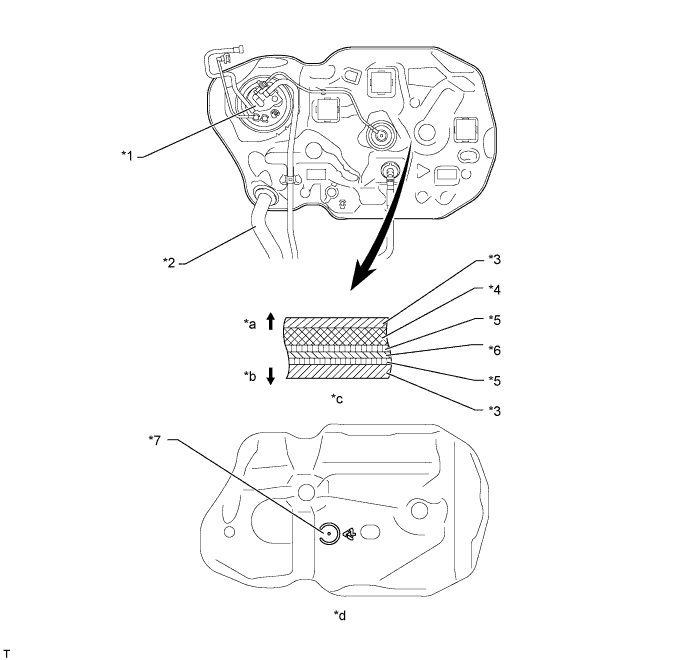
    1. A multiple layer plastic fuel tank assembly is used. This fuel tank assembly consists of 6 layers of 4 types of materials.


    2. A fuel drain mark has been provided at the lowest position of the fuel tank assembly. When dismantling (scrapping) the vehicle, drain fuel by drilling a hole at the drain mark.


      W101581E03


      Text in Illustration 
      *1
      Fuel Suction with Pump and Gauge Tube Assembly
      *2
      Fuel Inlet Pipe
      *3
      High Density Polyethylene (HDPE)
      *4
      Regrind Material
      *5
      Adhesive
      *6
      Ethylene Vinyl Alcohol Copolymer (EVOH)
      *7
      Fuel Drain Mark
      -
      -
      *a
      Exterior of Fuel Tank Assembly
      *b
      Interior of Fuel Tank Assembly
      *c
      Fuel Tank Wall Cross Section
      *d
      View from Bottom Side


  2. Fuel Suction with Pump and Gauge Tube Assembly


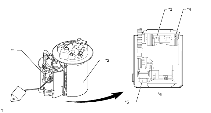
    1. A compact fuel pump, fuel filter, fuel pressure regulator assembly, fuel sender gauge assembly and charcoal canister are integrated into the fuel suction with pump and gauge tube assembly.


      W101582E02


      Text in Illustration 
      *1
      Fuel Sender Gauge Assembly
      *2
      Charcoal Canister
      *3
      Fuel Pump
      *4
      Fuel Filter
      *5
      Fuel Pressure Regulator Assembly
      -
      -
      *a
      Cross Section
      -
      -


  3. Fuel Delivery Pipe Sub-assembly


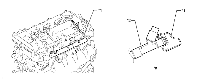
    1. A pressed steel fuel delivery pipe sub-assembly is used.


      W101541E02


      Text in Illustration 
      *1
      Fuel Delivery Pipe Sub-assembly
      *2
      Fuel Injector Assembly
      *a
      A-A Cross Section
      -
      -


  4. Fuel Injector Assembly


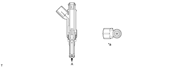
    1. The fuel injector assembly is shaped to form a long nozzle. This shortens the distance from the injector to intake valves, which helps to prevent the fuel from adhering to the intake port walls and reduces exhaust emissions.


      W101542E02


      Text in Illustration 
      *a
      View from A
      -
      -