DYNAMIC RADAR CRUISE CONTROL SYSTEM > DETAILS


FUNCTION OF MAIN COMPONENTS
  1. The main components in the dynamic radar cruise control system have the following functions:

    Component
    Function
    Millimeter Wave Radar Sensor
    Radiates millimeter radar waves forward, uses the reflected waves to detect the presence of a vehicle being driven ahead, the vehicle-to-vehicle distance, and the relative speed, and then transmits this information to the driving support ECU assembly.
    Driving Support ECU Assembly
    1. Calculates the motive force required to achieve the target vehicle speed/target vehicle-to-vehicle distance based on signals from switches, sensors and ECUs and transmits motive force request signals to the power management control ECU (to accelerate the vehicle in accordance with the motive force request) and the skid control ECU (to decelerate the vehicle in accordance with the motive force request).
    2. Determines presence of a preceding vehicle based on information from the millimeter wave radar sensor.
    3. Transmits control status display request signals, warning display request signals and diagnosis signals for the dynamic radar cruise control system.
    Cruise Control Switch
    ON-OFF Button
    Turns the cruise control system on and off.
    MODE Switch
    Switches between the constant speed control mode and vehicle-to-vehicle distance control mode.
    CANCEL Switch
    A cancel signal can be output to the driving support ECU assembly through the operation of this switch.
    +RES Switch
    The accelerate function and resuming of a preset speed can be performed by operating this switch. A signal is output to the driving support ECU assembly when this switch is operated.
    -SET Switch
    The decelerate function and vehicle speed setting resume signals are output to the driving support ECU assembly due to operation of this switch.
    Distance Control Switch
    While the system is in the vehicle-to-vehicle distance control mode, the driver can operate the distance control switch to select the vehicle-to-vehicle distance in 3 stages: long, middle, and short.
    Power Management Control ECU
    1. Increases and decreases the motive force in accordance with the motive force request signals transmitted by the driving support ECU assembly.
    2. Transmits the information about motive forces that are actually generated and that can be generated to the driving support ECU assembly.
    MG ECU
    Built into the inverter with converter assembly. Controls the motive force of MG2 in accordance with signals from the power management control ECU.
    ECM
    Actuates the throttle control motor in accordance with the signals from the power management control ECU.
    Skid Control ECU
    1. While the system is operating in vehicle-to-vehicle distance control mode, the skid control ECU performs brake control in accordance with request signals from the power management control ECU.
    2. Transmits signals such as wheel speed and estimated vehicle acceleration to the driving support ECU assembly.
    Combination Meter Assembly
    Cruise Control Indicator Light (Constant Speed Control Mode)
    1. Comes on when constant speed control mode is entered.
    2. Turns off if a malfunction occurs during constant speed control mode control.
    Cruise Control Indicator Light (Vehicle-to-vehicle Distance Control Mode)
    1. Comes on when the cruise control switch ON-OFF button is pressed to start the cruise control system.
    2. Turns off if a malfunction occurs during vehicle-to-vehicle distance control mode control.
    Master Warning Light
    Illuminates when there is a malfunction in the system.
    Buzzer
    If the driving support ECU assembly detects automatic cancel or warning signals while the vehicle is operating under cruise control, this buzzer sounds to inform the driver.
    Multi-information Display
    1. Displays the cruise control SET indication and set speed on the multi-information display when the vehicle speed is set.
    2. During dynamic radar cruise control operation, the multi-information display receives signals from the driving support ECU assembly, in order to display the system conditions.
    MG2
    Generates the motive force for the wheels.
    Throttle Control Motor
    Adjusts the throttle valve opening angle in accordance with signals from the ECM.
    Brake Actuator Assembly
    Actuates the brakes in accordance with the signals from the skid control ECU.
    Stop Light Control Relay
    Illuminates the stop light in accordance with the stop light illumination request signal from the skid control ECU.
    Skid Control Buzzer Assembly
    Sounds on receiving a signal from the skid control ECU and alerts the driver that the distance between vehicles is short.
    Speed Sensor
    Detects the wheel speed of each of the 4 wheels.
    Accelerator Pedal Sensor Assembly
    Detects the accelerator pedal depression degree and outputs it to the power management control ECU.
    Shift Lever Position Sensor
    Detects the shift position and transmits signals to the power management control ECU.
    Steering Angle Sensor
    Detects the angle and direction of steering and transmits signals to the driving support ECU assembly.
    Yawrate Sensor
    Detects the yawrate of the vehicle and transmits signals to the driving support ECU assembly.
    Stop Light Switch Assembly
    Detects the pressing of the brake pedal and transmits its signal to the driving support ECU assembly.


SYSTEM CONTROL
  1. The dynamic radar cruise control system is controlled by the driving support ECU assembly. The driving support ECU assembly increases and decreases the vehicle speed by controlling the engine, MG2 and brake through the motive force request signals.

  2. The combination meter assembly informs the driver of the control conditions.

  3. The cruise control switch (mode switch) is used for switching between the constant speed control mode and the vehicle-to-vehicle distance control mode. The mode in which the cruise control system starts is the vehicle-to-vehicle distance control mode.


  4. As in the dynamic radar cruise control system, the constant control mode is controlled by the driving support ECU assembly, which outputs signals to the MG ECU.


    Y109751E01

  5. The Vehicle-to-vehicle distance control mode is controlled by the millimeter wave radar sensor and driving support ECU assembly. Thus, the signals are output to the actuators and the ECU while exchanging data as indicated above.


FUNCTION
  1. Function List

    1. The control of the dynamic radar cruise control system varies depending on the mode:
      A: Constant Speed Control Mode
      B: Vehicle-to-vehicle Distance Control Mode

      Function
      Outline
      Mode
      A
      B
      Constant Speed Control
      Controls the motive force through the power management control ECU and skid control ECU, and adjusts the vehicle speed to the set vehicle speed.
      X
      X
      Deceleration Control
      Performs engine, MG2 and brake control in order to decelerate the vehicle so that the vehicle-to-vehicle distance between the driver's own vehicle and the vehicle ahead equals the set distance.
      -
      X
      Follow-up Control
      After performing deceleration control, the driver's own vehicle follows the vehicle ahead in order to maintain the proper vehicle-to-vehicle distance in accordance with the vehicle speed.
      -
      X
      Acceleration Control
      Accelerates the vehicle in order to attain the set vehicle speed if the vehicle ahead or the driver's own vehicle has changed lanes.
      -
      X
      Set Control
      1. While this system fulfils the following conditions, and the cruise control switch is moved to the -SET side and released, the driving support ECU assembly stores the vehicle speed and maintains the vehicle constantly at that speed.
        1. ON-OFF button on the cruise control switch is pressed.
      X
      X
      1. The vehicle is running at an approximate speed of between 50 km/h (30 mph) and 200 km/h (125 mph).
      X
      -
      1. The vehicle is running at an approximate speed of between 50 km/h (30 mph) and 170 km/h (105 mph).
      -
      X
      Low Speed Limit Control
      The low speed limit is the lowest speed that cruise control can be set at and it is designed to be approximately 40 km/h (25 mph). The cruise control cannot be set below that speed. If the vehicle speed drops below that speed while running in the cruise control, the cruise control will be cancelled automatically. The set vehicle speed is kept in memory.
      X
      X
      COAST (-) Switch Control
      When the cruise control switch is held to the -SET side, the vehicle speed and the set vehicle speed change as follows, according to the mode:
      X
      X
      1. The vehicle decelerates constantly.
      2. The set vehicle speed changes to the speed at which the switch is released.
      X
      -
      1. The set vehicle speed decreases in increments of 5 km/h or 5 mph. (Example: 103 → 100 → 95 km/h [mph])
      2. The vehicle will remain at the speed that the vehicle is traveling at when the COAST switch is released.
      -
      X
      Tap Down Control
      When the cruise control switch is moved momentarily (approximately 0.6 seconds or less) to the -SET side, the vehicle speed and the set vehicle speed change as follows, according to the mode:
      X
      X
      1. The vehicle will decelerate in increments of approximately 1.6 km/h (1 mph) for each time the switch is moved.
      2. However, if the difference between the actual vehicle speed and the set vehicle speed is greater than 5 km/h (3 mph), the set vehicle speed will change to the speed at which the vehicle was traveling at when the switch is released.
      X
      -
      1. For the European models, the vehicle will decelerate in increments of approximately 5 km/h or 5mph for each time the switch was moved.
      -
      X
      1. The vehicle will decelerate in increments of approximately 1 km/h or 1 mph for each time the switch was moved.
      ACC (+) Switch Control
      When the cruise control switch is held to the +RES side, the vehicle speed and the set vehicle speed change as follows, according to the mode:
      X
      X
      1. The vehicle will accelerate constantly.
      2. The set vehicle speed changes to the speed at which the switch is released.
      X
      -
      1. The set vehicle speed increases in increments of 5 km/h or 5 mph. (Example: 103 → 105 → 110 km/h [mph])
      2. The vehicle will accelerate to the speed that is set at the time the switch is released. However, only the set vehicle speed will change during follow-up control.
      -
      X
      Tap Up Control
      When the cruise control switch is moved momentarily (approximately 0.6 seconds or less) to the +RES side, the vehicle speed and the set vehicle speed change as follows:
      X
      X
      1. The vehicle will accelerate in increments of approximately 1.6 km/h (1 mph) for each time the switch was moved.
      2. However, if the difference between the actual vehicle speed and the set vehicle speed is greater than 5 km/h (3 mph), the set vehicle speed will not change.
      X
      -
      1. For the European models, the vehicle will accelerate in increments of approximately 5 km/h or 5mph for each time the switch was moved
      -
      X
      1. The vehicle will accelerate in increments of approximately 1 km/h or 1 mph for each time the switch was moved.
      RES Switch Control
      If the vehicle speed is above the low speed limit, the cruise control resumes operation (when the cruise control switch is subsequently moved to the +RES side) to reach the vehicle speed that was set at the time the driver canceled cruise control.
      X
      X
      If the vehicle ahead changes driving lanes during follow-up control, the vehicle speed is gradually increased to the set vehicle speed. At this time, the vehicle speed can be increased promptly by moving the cruise control switch to the +RES side.
      -
      X
      Manual Cancel Control
      1. If any of the following signals are sent to the power management control ECU, the cruise control is cancelled accordingly.
        1. stop light switch assembly on signal (The brake pedal is depressed.)
        2. D position off signal (The shift lever is moved from D to N or B.)
        3. CANCEL switch on signal (The cruise control switch moved to the CANCEL side.)
        4. Cruise control switch (ON-OFF button) off signal
        5. VSC operation
      X
      X
      Automatic Cancel Control
      When an automatic cancel signal is sent to the power management control ECU, cruise control operation is canceled. At this time, the type of warning sent to the driver and the control resumption condition varies according to the cancel signal.
      X
      X
      Mode Switching Control
      1. The following procedure switches the mode:
        1. Turn the cruise control on using the ON-OFF button on the switch (the cruise control will start in the vehicle-to-vehicle distance control mode).
        2. Hold the cruise control switch to the MODE side for approximately 1 second or more.
      2. If the switch is moved to any other side before switching modes, switch the cruise control system off and then perform steps (a) and (b) again.
      X
      X

      1. X: Available
      2. -: Not Available


  2. Constant Speed Control

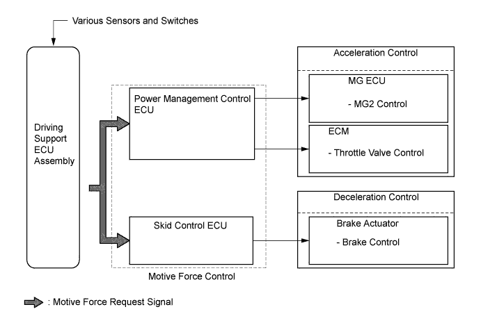
    1. The driving support ECU assembly compares the actual vehicle speed (wheel speed signal from the skid control ECU) with the set vehicle speed under constant speed control in each control mode. When the actual vehicle speed differs from the set vehicle speed, the driving support ECU assembly calculates the motive force required to achieve the set vehicle speed and transmits motive force request signals to the power management control ECU, thus controlling the motive force optimally and adjusting the actual vehicle speed to the set vehicle speed.


    2. In vehicle-to-vehicle distance control mode, the driving support ECU assembly performs deceleration control or follow-up control or acceleration control based on the information about the vehicle ahead transmitted from the millimeter wave radar sensor.


      Y102740E02


  3. Deceleration Control

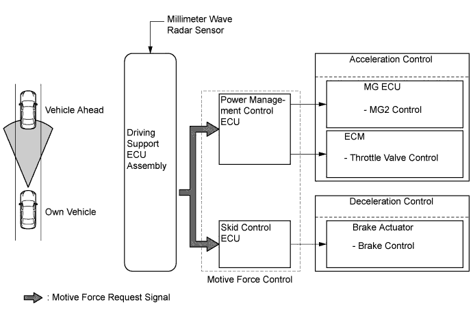
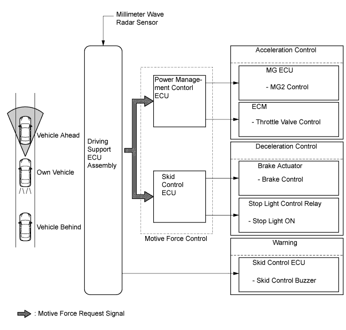
    1. The driving support ECU assembly calculates the target deceleration rate in accordance with signals from the millimeter wave radar sensor, and transmits a motive force request signal to the power management control ECU and the skid control ECU. Upon receiving this signal, these ECUs control the motive force and decelerate the vehicle.


    2. This control is not performed in the presence of a parked vehicle or object, or below the settable vehicle speed range.


      Y102742E02

    3. If the driving support ECU assembly determines that further deceleration is necessary, it transmits a brake request signal to the skid control ECU. Upon receiving this signal, the skid control ECU then activates the brake actuator assembly to apply the brakes.


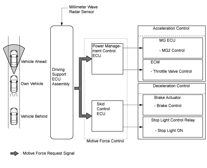
    4. At this time, if the deceleration rate is higher than a predetermined value, the skid control ECU outputs a stop light illumination request signal to the stop light control relay, in order to inform anyone who might be following the vehicle.


      Y102743E03


    5. If the vehicle is not decelerating adequately, the skid control ECU sounds the skid control buzzer assembly based on the request signal from the driving support ECU assembly to urge the driver to depress the brake pedal.


      Y102744E03


  4. Follow-up Control

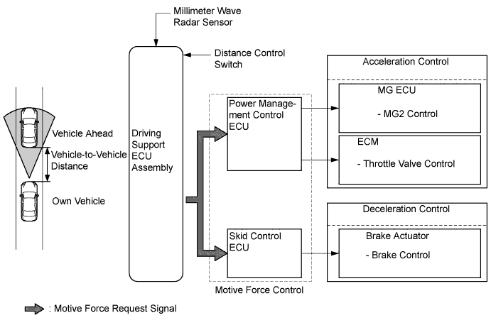
    1. After performing deceleration control, the driving support ECU assembly transmits a motive force request signal to the power management control ECU and the skid control ECU so that the vehicle can follow the vehicle ahead while maintaining the proper vehicle-to-vehicle distance according to the vehicle speed. Upon receiving this signal, these ECUs control the motive force in order to perform follow-up control.


    2. 3 stages (long, middle, and short) of vehicle-to-vehicle distance can be selected by operating the distance control switch.


      Y102745E02


  5. Acceleration Control


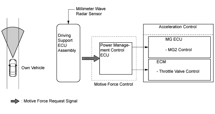
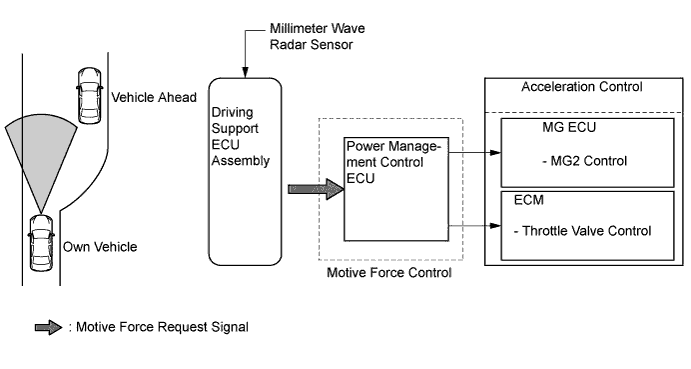
    1. If the driving support ECU assembly detects that either the vehicle ahead or own vehicle has changed lanes, a motive force request signal is transmitted to the power management control ECU in order to attain the set vehicle speed. Upon receiving this signal, the power management control ECU controls the motive force of the engine and MG2 in order to perform acceleration control.


      Y102746E02

  6. Automatic Cancel Control

    1. If any of the conditions listed below occur while the vehicle is being driven using cruise control, the cruise control will be canceled. Then, the following warning items will appear for the driver.

      Constant Speed Control Mode: 
      Description of Malfunction
      Warning
      Multi-information Display
      Master Warning Light
      Buzzer
      Cruise Control Indicator Light (Constant Speed Control Mode)
      1. If the condition listed below occur, the power management control ECU clears the set vehicle speed and cancels the cruise control.
        1. Malfunction of the vehicle speed signal
        2. An open or short circuit in the stop light switch assembly
      1. The cruise control is prohibited until the conditions are remedied or the cruise control system is turned off and back on again using the ON-OFF button on the cruise control switch.
      CHECK CRUISE CONTROL SYSTEM
      Illuminates
      Sounds Once
      Turns off
      1. If the condition listed below occur, the power management control ECU clears the set vehicle speed and cancels the cruise control.
        1. Malfunction in the hybrid system
      1. The cruise control is prohibited until the conditions are remedied or the cruise control system is turned off and back on again using the ON-OFF button on the cruise control switch.
      -
      -
      -
      Turns off
      1. If the condition listed below occurs, the power management control ECU clears the set vehicle speed and cancels the cruise control.
        1. The vehicle speed drops more than 16 km/h (10 mph) below the set vehicle speed.
      -
      -
      -
      Turns off
      1. If the condition listed below occurs, the power management control ECU cancels the cruise control while retaining the set vehicle speed in its memory.
        1. The vehicle speed drops below low speed limit (approximately 40 km/h [25 mph]).
      -
      -
      -
      Turns off

      Vehicle-to-vehicle Distance Control Mode: 
      Description of Malfunction
      Warning
      Multi-information Display
      Master Warning Light
      Buzzer
      Cruise Control Indicator Light (Vehicle-to-vehicle Distance Control Mode)
      1. If any of the conditions listed below occurs, the power management control ECU clears the set vehicle speed and cancels the cruise control.
        1. Malfunction of the vehicle speed signal
        2. An open or short circuit in the stop light switch assembly
      1. The cruise control is prohibited until the conditions are remedied or the cruise control system is turned off and back on again using the ON-OFF button on the cruise control switch.
      CHECK CRUISE CONTROL SYSTEM
      Illuminates
      Sounds Once
      Turns off
      1. If the condition listed below occur, the power management control ECU clears the set vehicle speed and cancels the cruise control.
        1. Malfunction in the hybrid system
      1. The cruise control is prohibited until the conditions are remedied or the cruise control system is turned off and back on again using the ON-OFF button on the cruise control switch.
      -
      -
      -
      Turns off
      1. If any of the conditions listed below occur, the power management control ECU clears the set vehicle speed and cancels the cruise control.
        1. Malfunction of the millimeter wave radar sensor.
        2. Displacement of the axis of the millimeter wave radar sensor.
        3. Malfunction in the dynamic radar cruise control system other than those given above.
      1. The cruise control is prohibited until the power switch is turned on again.
      CHECK CRUISE CONTROL SYSTEM
      Illuminates
      Sounds Once
      Turns off
      1. If the condition listed below occurs, the power management control ECU cancels the cruise control while retaining the set vehicle speed in its memory.
        1. The millimeter wave radar sensor is dirty.
        2. The radiator grill is dirty.
      1. The cruise control is prohibited until the conditions are remedied or the cruise control system is turned off and back on again using the ON-OFF button on the cruise control switch.
      CLEAN RADAR SENSOR
      Illuminates
      Sounds Once
      Turns off
      1. If any of the conditions listed below occur, the power management control ECU cancels the cruise control while retaining the set vehicle speed in its memory.
        1. The wipers operate at HI speed.
        2. The measurement becomes extremely unstable due to poor weather conditions.
      1. The cruise control is prohibited until the conditions are remedied or the cruise control system is turned off and back on again using the ON-OFF button on the cruise control switch.
      CRUISE CONTROL NOT AVAILABLE
      Illuminates
      Sounds Once
      Turns off
      1. If the condition listed below occurs, the power management control ECU cancels the cruise control while retaining the set vehicle speed in its memory.
        1. The vehicle speed drops below low speed limit (approximately 40 km/h [25 mph]).
      -
      -
      Sounds Twice
      Turns off


CONSTRUCTION


  1. Cruise Control Switch

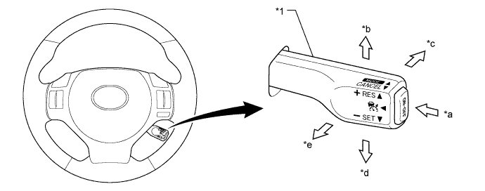
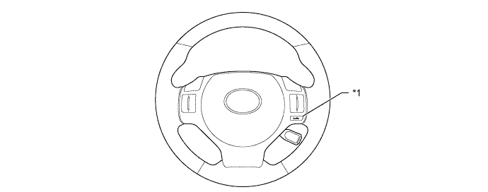
    1. The cruise control switch consists of the ON-OFF button, +RES, MODE, -SET and CANCEL switches. The +RES, MODE, -SET and CANCEL switches are operated by moving the lever in the 4 directions indicated.


    2. The cruise control switch is an automatic reset (normally open) type that turns on only when the switch is being operated and turns off as soon as the driver releases the switch. Furthermore, the functions of the control switch are active only when the cruise control system has been turned on using the ON-OFF button on the cruise control switch.


      W103899E01


      Text in Illustration 
      *1
      Cruise Control Switch
      -
      -
      *a
      ON-OFF Button
      *b
      +RES Switch
      *c
      MODE Switch
      *d
      -SET Switch
      *e
      CANCEL Switch
      -
      -


  2. Distance Control Switch


    1. While the vehicle is being driven in vehicle-to-vehicle distance control mode, the vehicle-to-vehicle distance setting changes as follows each time the distance control switch is pressed; long → middle → short.


      Y109493E01


      Text in Illustration 
      *1
      Distance Control Switch
      -
      -

    2. If the power switch is turned off and back to on (IG), the system will default to "long".

    3. The vehicle-to-vehicle distance is set as follows:

      Mode
      Vehicle-to-vehicle Distance*
      Long
      Approximately 50 m (160 ft.)
      Middle
      Approximately 40 m (130 ft.)
      Short
      Approximately 30 m (100 ft.)

      HINT:
      *: While driving at a vehicle speed of 80 km/h (50 mph).


  3. Millimeter Wave Radar Sensor

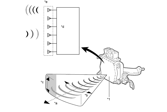
    1. The millimeter wave radar sensor consists of a millimeter wave radar circuit, signal processing circuit, and CPU.

    2. The millimeter wave radar outputs waves when the vehicle speed is above 0 km/h (0 mph), and not when the vehicle speed is at 0 km/h (0 mph). The millimeter wave radar uses frequencies in the 76 GHz band.

    3. The reception antennas receive the millimeter wave radar waves that have been reflected.


    4. The signal processing circuit detects the distance, relative speed, and the direction of the object by generating millimeter wave radar waves and calculating the signals received by the reception antennas. Then, it transmits this information to the driving support ECU assembly.


      Y109576E01


      Text in Illustration 
      *1
      Millimeter Wave Radar Sensor
      -
      -
      *a
      Detection Distance: Approximately 150 m
      *b
      Horizontal Angle: About 20°
      *c
      Vertical Angle: About 4°
      *d
      Signal Processing Circuit
      *e
      Millimeter Wave Radar Circuit
      -
      -


    5. The distance to the object, azimuth, and relative speed are calculated from the information that is provided by the reflection millimeter wave radar as described below.

      Item
      Calculation Method
      Distance
      Calculated from the length of time that has elapsed from the time the waves of the millimeter wave radar have been emitted, until the waves reflected by the millimeter wave radar are received. The detection distance is approximately 150 m (490 ft.).
      Azimuth
      Calculated from the angle of the waves reflected by the millimeter wave radar that have been received. The detection angle has a horizontal angle of approximately 20° and a vertical angle of approximately 8°.
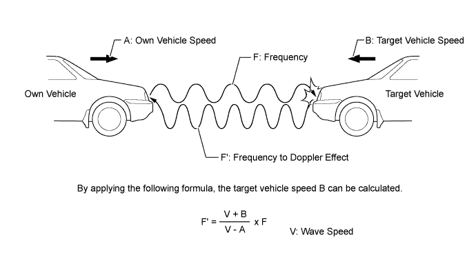
      Relative Speed
      Calculated by utilizing the changes (Doppler effect*) that occur in the frequencies of the reflected millimeter wave radar waves.

      HINT:
      *: The Doppler effect causes the observer to perceive the radio waves emitted by a moving object to be of higher frequencies as it approaches, and to be of lower frequencies at it recedes.


      Y102750E06

      HINT:
      An SST is used if radar axis adjustment is needed. For details, refer to the Repair Manual.


OPERATION
  1. Combination Meter Assembly

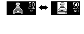
    1. The combination meter assembly provides a master warning light, cruise control indicator light (constant speed control mode), cruise control indicator light (vehicle-to-vehicle distance control mode), cruise control SET indication, buzzer, and multi-information display to provide warnings and messages regarding the dynamic radar cruise control system.

    2. The multi-information display displays the set vehicle speed, vehicle ahead mark, and warning message.

    3. Examples are shown below for the illumination or display of each indicator light, warning light or multi-information display.

      Constant Speed Control Mode: 
      Condition
      Multi-information Display
      Cruise Control Indicator Light (Constant Speed Control Mode)
      SET
      (message displayed on multi-information display)
      Master Warning Light
      Buzzer
      Being Controlled
      Y109542
      Illuminates
      Displayed
      -
      -
      System Check
      Y109506
      Turns off
      -
      Illuminates
      Sounds Once

      Vehicle-to-vehicle Distance Control Mode: 
      Condition
      Multi-information Display
      Cruise Control Indicator Light (Vehicle-to-vehicle Distance Control Mode)
      SET
      (message displayed on multi-information display)
      Master Warning Light
      Buzzer
      Set Standby
      Y109496
      Illuminates
      -
      -
      -
      Under Constant Speed Control (No Vehicle Ahead, Short)
      Y109536
      Illuminates
      Displayed
      -
      -
      Under Follow-up Control (Vehicle Ahead, Middle)
      Y109539
      Illuminates
      Displayed
      -
      -
      Deceleration Control/Vehicle Approach Warning (Vehicle Ahead, Long)
      Y109543
      Illuminates
      Displayed
      -
      Skid Control Buzzer Sounds Continuously
      The vehicles in the display are highlighted at the 0.5-second intervals.
      Millimeter Wave Radar Sensor is Dirty.
      Y109504
      Turns off
      -
      Illuminates
      Sounds Once
      Poor Weather Conditions
      Y109505
      Turns off
      -
      Illuminates
      Sounds Once
      System Check
      Y109506
      Turns off
      -
      Illuminates
      Sounds Once
      Beam Axis Adjustment
      Y109503
      Turns off
      -
      -
      Skid Control Buzzer Sounds Once


DIAGNOSIS
  1. If a malfunction occurs in the dynamic radar cruise control system during cruise control operation, the driving support ECU assembly cancels the cruise control and turns off the cruise control indicator light (constant speed control mode) or cruise control indicator light (vehicle-to-vehicle distance control mode) to inform the driver of the malfunction. At the same time, the malfunction is stored in memory as a Diagnostic Trouble Code (DTC).

  2. The DTC can be read when the intelligent tester is connected to DLC3. The intelligent tester can be used to read the 5-digit codes. For details, refer to the Repair Manual.