HYBRID CONTROL SYSTEM > GENERAL


OUTLINE
  1. The hybrid system of this hybrid vehicle employs the LEXUS Hybrid Drive under the "Hybrid Synergy Drive" concept*.

  2. Hybrid vehicles uses a combination of 2 kinds of power sources, such as an engine and HV battery, so as to take advantage of the benefits provided by each power source while compensating for each other's shortcomings. As a result, efficient operation is achieved.

  3. Hybrid vehicles do not need their batteries to be charged externally unlike existing electric-only vehicles. Therefore, special infrastructure is not required to use hybrid vehicles.

  4. Technical development of power units (such as an engine or fuel cell) is advancing in various fields. The hybrid system is a flexible system that uses a high-efficiency power unit and electric motors.

  5. Hybrid vehicles have high-voltage electrical circuits. Hybrid vehicles have been developed with consideration given to the protection of drivers and technicians against electrocution.

    HINT:
    *: The "Hybrid Synergy Drive" concept consists of 4 key benefits: Fuel efficiency, low emissions, seamless acceleration, and silent performance.


SPECIFICATION
  1. Motor Generator

    Item
    Specification
    MG1
    MG2
    Type
    Permanent Magnet Motor
    Permanent Magnet Motor
    Function
    Generate, Engine Starter
    Generate, Drive Wheels
    Maximum System Voltage
    V
    DC 650
    DC 650
    Maximum Output
    kW (HP)
    -
    60 (80)
    Maximum Torque
    N*m (ft.*lbf)
    -
    207 (153)
    Cooling System
    Water-cooled
    Air-cooled

  2. Inverter with Converter Assembly

    Item
    Specification
    Boost Converter
    Rated Voltage (Inverter Side)
    V
    DC 650
    Rated Voltage (HV Battery Side)
    V
    DC 201.6
    DC-DC Converter
    Rated Output Voltage
    V
    DC 13.5 to 15.0 (normal condition)
    DC 11.5 (activated at low temperatures)
    Maximum Output Current
    A
    120

  3. HV Battery

    Item
    Specification
    Type
    Nickel Metal Hydride (Ni-MH) Battery
    Cell Quantity
    168 Cells (6 Cells x 28 Modules)
    Nominal Voltage
    V
    201.6
    Battery Capacity (3HR)
    Ah
    6.5

  4. Cooling System (for Inverter with Converter Assembly and MG1)

    Item
    Specification
    Inverter Water Pump Assembly
    Motor Type
    Brushless
    Discharge Volume
    Liter (US qts, Imp. qts)
    10 (10.6, 8.8) /min. or greater
    Coolant
    Type
    Toyota Genuine Super Long Life Coolant (SLLC)
    Color
    Pink
    Capacity
    Liter (US qts, Imp. qts)
    2.1 (2.2, 1.8)
    Maintenance Intervals
    First Time
    km (miles)
    240000 (150000)
    Subsequent
    km (miles)
    Every 80000 (50000)

  5. Cooling System (for HV Battery)

    Item
    Specification
    Battery Cooling Blower Assembly
    Motor Type
    Brushless
    Fan Type
    Sirocco Fan
    Air Flow Volume
    m3/h
    138


MAIN FEATURES
  1. The LEXUS Hybrid Drive control has the following features.

    Item
    Outline
    Idle Stop
    Idling of the engine is automatically stopped (idle stop) to reduce energy loss.
    EV Drive
    (Efficient Drive Control)
    This allows the vehicle to be driven using only the electric motor when engine efficiency is low. In addition, electricity is generated when engine efficiency is high. Control is performed to maximize the total efficiency of the vehicle.
    EV Drive Mode
    If the driver operates the switch and the operating conditions are being met, the vehicle can run on only the electric motor.
    Motor Assist
    The electric motor supplements the engine power when accelerating.
    Regenerative Braking
    (Energy Regeneration)
    During deceleration and while depressing the brake pedal, part of the energy that was lost as heat is collected as electrical energy to be reused, such as for motor power.


  2. The mechanism of the LEXUS Hybrid Drive is as follows.


    1. The LEXUS Hybrid Drive consists of mainly the engine, hybrid vehicle transaxle assembly, inverter with converter assembly and HV battery, and employs the series/parallel-type hybrid system.
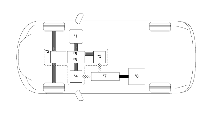

      W101195E02


      Text in Illustration 
      *1
      Engine
      *2
      Hybrid Vehicle Transaxle Assembly
      *3
      Motor Generator 1 (MG1)
      *4
      Motor Generator 2 (MG2)
      *5
      Power Split Planetary Gear Unit (Compound Gear Unit)
      *6
      Motor Speed Reduction Planetary Gear Unit (Compound Gear Unit)
      *7
      Inverter with Converter Assembly
      *8
      HV Battery
      V100143
      Electrical Power Path (DC)
      V100155
      Electrical Power Path (AC)
      V100144
      Mechanical Power Path
      -
      -

      HINT:
      Generally, there are 3 types of hybrid systems: A series-type hybrid system, a parallel-type hybrid system and a series/parallel-type hybrid system.


      1. In a series-type hybrid system, the motor rotates the wheels, and the engine, using a generator, acts as an electric power source for the motor.
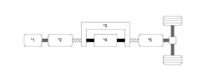

        W101596E01


        Text in Illustration 
        *1
        Engine
        *2
        Generator
        *3
        Inverter
        *4
        HV Battery
        *5
        Motor
        -
        -
        V100143
        Electrical Power Path (DC)
        V100155
        Electrical Power Path (AC)
        V100144
        Mechanical Power Path
        -
        -

      2. In a parallel-type hybrid system, both the engine and the motor generator directly rotate the wheels. In addition to supplementing the power of the engine, the motor generator can also serve as a generator to charge the HV battery while the vehicle is in motion. Driving the vehicle only with the motor generator is also possible.
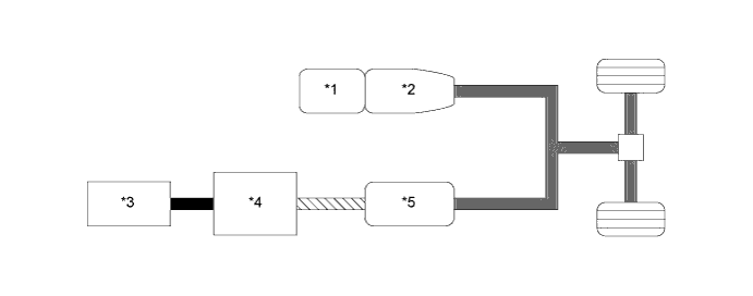

        W101597E01


        Text in Illustration 
        *1
        Engine
        *2
        Transmission
        *3
        HV Battery
        *4
        Inverter
        *5
        Motor Generator
        -
        -
        V100143
        Electrical Power Path (DC)
        V100155
        Electrical Power Path (AC)
        V100144
        Mechanical Power Path
        -
        -

      3. In a series/parallel-type hybrid system, aspects of both a series-type hybrid system and a parallel-type hybrid system are combined. The system has 2 motor generators. Electricity can be generated by motor generator 1 using engine power. The generated electricity is used to charge the HV battery and also to power motor generator 2.
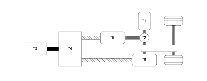

        W101598E01


        Text in Illustration 
        *1
        Engine
        *2
        Power Split Planetary Gear Unit
        *3
        HV Battery
        *4
        Inverter
        *5
        Motor Generator 1
        *6
        Motor Generator 2
        V100143
        Electrical Power Path (DC)
        V100155
        Electrical Power Path (AC)
        V100144
        Mechanical Power Path
        -
        -

    2. This system optimally performs cooperative control of the 2ZR-FXE engine, and Motor Generator 1 (MG1) and Motor Generator 2 (MG2) in the P410 hybrid vehicle transaxle assembly that provides excellent transmission performance.

    3. The system has 2 batteries that are used in different purposes. One is the HV battery (nominal voltage of DC 201.6 V) that stores electrical power to drive the vehicle, and the other is the auxiliary battery (nominal voltage of DC 12 V) that supplies electrical power to the electrical components.

    4. Furthermore, it uses a variable-voltage system consisting of a high-output HV battery with a nominal voltage of DC 201.6 V, a boost converter that boosts the operating voltage of MG1 and MG2 to a maximum voltage of DC 650 V, and an inverter that converts direct current and alternating current.


    5. Since hybrid vehicles are not equipped with a conventional alternator, the high-voltage from the HV battery is dropped to approximately DC 14 V using a DC-DC converter in order to charge the auxiliary battery. Also, the HV battery regularly charges and discharges within the constant State of Charge (SOC) range while the vehicle is running, thus, recharging from external power sources is not necessary.
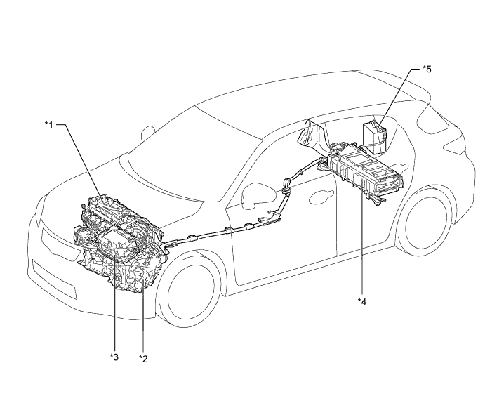

      W103897E01


      Text in Illustration 
      *1
      2ZR-FXE Engine
      *2
      P410 Hybrid Vehicle Transaxle Assembly
      - Motor Generator 1 (MG1)
      - Motor Generator 2 (MG2)
      *3
      Inverter with Converter Assembly
      - Inverter
      - Boost Converter
      - DC-DC Converter
      *4
      HV Battery Assembly
      *5
      Auxiliary Battery
      -
      -


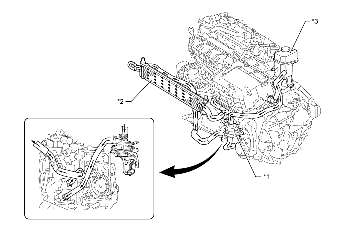
    6. A cooling system that is independent from the engine cooling system is provided to cool the inverter with converter assembly and MG1.

      W103898E01


      Text in Illustration 
      *1
      Inverter Water Pump Assembly
      *2
      Radiator Assembly
      *3
      Inverter Reserve Tank
      -
      -
      V100135
      HV Coolant Flow
      -
      -


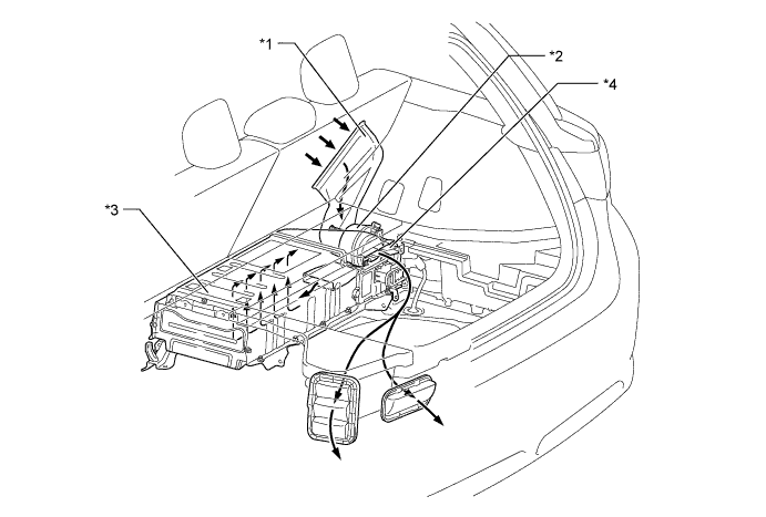
    7. To ensure the proper performance of the HV battery while it generates heat during the repetitive charge and discharge cycles, a dedicated cooling system is used for the HV battery.

      W103900E01


      Text in Illustration 
      *1
      Intake Air Duct
      *2
      Battery Cooling Blower Assembly
      *3
      HV Battery
      *4
      Exhaust Air Duct
      V100135
      Cooling Air Flow
      -
      -


PRECAUTION
  1. Hybrid Vehicle High-voltage Safety Measures

    1. High-voltage safety is comprised of 2 points: "Insulation of High-voltage Circuits" and "Cut-off of High-voltage Circuits". The hybrid system also detects whether or not a decrease in insulation resistance has occurred between the high-voltage system and body ground.


  2. Insulation of High-voltage Circuits

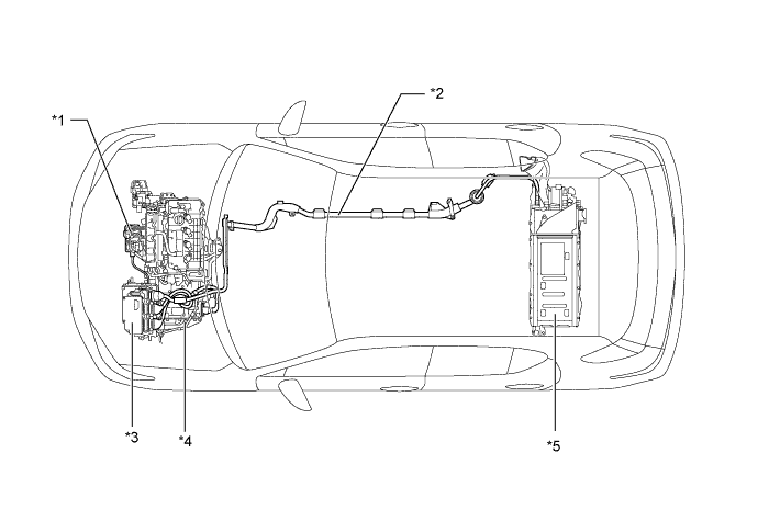
    1. High-voltage circuits are used between the HV battery, inverter with converter assembly, hybrid vehicle transaxle assembly and compressor with motor assembly. Each of these items is connected by the power cables and is electrically insulated using cases and covers.


    2. Cables are also shielded using a mesh conductor built into the electrical insulation of the wires. The shielding is grounded to the chassis of the vehicle and the main purpose is to prevent electromagnetic interference.


      W103901E01


      Text in Illustration 
      *1
      Compressor with Motor Assembly
      *2
      Power Cable
      *3
      Inverter with Converter Assembly
      *4
      Hybrid Vehicle Transaxle Assembly
      *5
      HV Battery Assembly
      -
      -


  3. Cut-off of High-voltage Circuits


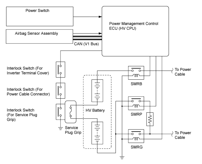
    1. When any of the conditions below occurs, the System Main Relays (SMRs) are automatically shut off by the power management control ECU (HV CPU).

      1. Power switch is off.
      2. Any airbag is deployed.
      3. Inverter terminal cover is removed (interlock circuit is opened).
      4. Power cable connector is disconnected (interlock circuit is opened).
      5. Service plug grip handle is being unlocked (interlock circuit is opened).
      6. A specified malfunction occurs.

      W103197E04


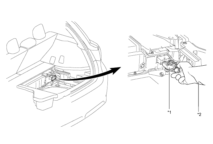
    2. By removing the service plug grip before performing any inspection or service, the high-voltage circuit is shut off at the intermediate position of the HV battery, thus ensuring safety during service.


      W103903E01


      Text in Illustration 
      *1
      Service Plug Grip
      *2
      Insulated Gloves

      CAUTION:
      A charge remains in the high-voltage capacitor in the inverter with converter assembly after the high-voltage circuits are shut down. When servicing a hybrid vehicle, after the service plug grip is removed, wait at least 10 minutes to allow the capacitor to discharge before beginning work.

      NOTICE:
      1. The service plug grip should never be removed when the system is in the READY-on state.
      2. After removing the service plug grip, turning the power switch on (READY) may cause a malfunction. Do not turn the power switch on (READY) unless instructed by the Repair Manual.

  4. HV Battery Handling Precautions

    1. HV battery electrolyte is a highly alkaline potassium hydroxide solution (odorless, transparent, and colorless). Careless handling of the HV battery is very dangerous. Handle the HV battery properly according to the procedure below.

      Item
      Procedure
      When there is liquid leakage present in the area of the HV battery
      1. Neutralize it with a saturated mixture of boric acid and water.
      2. After litmus paper has been used to determine that the mixture is neutral, wipe it up with rags or waste cloth.
      When battery electrolyte gets on skin, eyes etc.*
      1. Flush it with a diluted solution of boric acid and water, or with a large amount of water.
      2. Remove contaminated clothes at once.
      When a vehicle is scrapped
      Remove the HV battery from the vehicle for collection via the specified route.
      When the HV battery is stored
      The HV battery should not be left in a damp or humid location.
      Prevention of the HV battery discharge or damage when a vehicle is stored for a long time
      1. Disconnect the auxiliary battery negative terminal.
      2. When in storage, the HV battery should be charged every 2 months. Using the following procedure, charge the HV battery with the vehicle.
        1. Connect the negative terminal of the auxiliary battery.
        2. Turn the power switch on (IG) for 3 minutes, do not apply any electrical loads. (This operation is needed to allow the power management control ECU (HV CPU) to detect the correct SOC.)
        3. Enter the READY-on state. After the engine starts, leave it running for 30 minutes to charge the HV battery .If the engine does not start or intermittently stops within 30 minutes, stop the operation at that time. (The HV battery does not need to be charged.)

      CAUTION:
      *: If you get electrolyte in your eyes, shout loudly for help, do not rub your eyes, rinse your eyes with large amount of water and seek medical attention immediately.